R8C/13 Group
• FMR40 bit
17.4 CPU Rewrite Mode
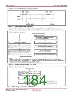
The erase-suspend function is enabled by setting the FMR40 bit to “1” (valid).
• FMR41 bit
In EW0 mode, the flash module goes to erase-suspend mode when the FMR41 bit is set to
“1”. In EW1 mode, the FMR41 bit is automatically set to “1” (erase-suspend requested) when
an enabled interrupt occurred, and then the flash module goes to erase-suspend mode.
The auto-erase operation restarts when the FMR41 bit is set to “0” (erase restart).
• FMR46 bit
The FMR46 bit is set to “0”(disables reading) during auto-erase execution and set to “1”(en-
ables reading) during erase-suspend mode. Do not access to the flash memory when this bit
is set to “0”.
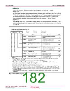
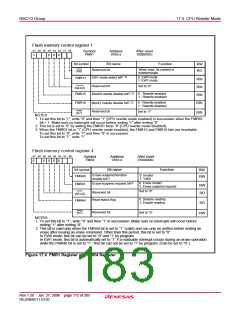
Flash memory control register 0
b7 b6 b5 b4 b3 b2 b1 b0
Symbol
FMR0
Address
01B716
After reset
00000001
2
0
0
Bit symbol
Bit name
Function
RW
RO
0: Busy (being written or erased)
1: Ready
RY/BY status flag
FMR00
FMR01
0: Disable CPU rewrite mode
1: Enable CPU rewrite mode
CPU rewrite mode
select bit(1, 6)
RW
RW
Block0 and 1 rewrite enable
bit(2, 6, 7)
0: Rewrite disabled
1: Rewrite enabled
FMR02
FMSTP
0: Enable flash memory operation
1: Stops flash memory operation
(placed in low power mode,
flash memory initialized)
Flash memory stop bit(3, 5, 6)
RW
RW
Reserved bit
Set to “0”
(b5-b4)
FMR06
Program status flag(4)
0: Terminated normally
1: Terminated in error
RO
RO
0: Terminated normally
1: Terminated in error
Erase status flag(4)
FMR07
NOTES:
1. To set this bit to “1”, write “0” and then “1” in succession. Make sure no interrupts will occur before
writing “1” after writing “0”.
Set the microcomputer in read array mode before writing “0” to this bit.
2. To set this bit to “1”, write “0” and then “1” in succession when the FMR01 bit = 1. Make sure no
interrupts will occur before writing “1” after writing “0”.
3. Write to this bit from a program in other than the flash memory.
4. This flag is set to “0” by executing the Clear Status command.
5. Effective when the FMR01 bit = 1 (CPU rewrite mode). If the FMR01 bit = 0, although the FMSTP bit
can be set to “1” by writing “1”, the flash memory is neither placed in low power mode nor initialized.
6. Use the bit process instruction to set the FMR01, FMR02 and FMSTP bits (Refer to “R8C/Tiny Series
Software Manual”.
7. When setting the FMR01 bit to “0” (disable CPU rewrite mode), the FMR02 bit is set to “0” (rewrite
disabled).
Figure 17.3 FMR0 Register
Rev.1.20 Jan 27, 2006 page 171 of 205
REJ09B0111-0120

 RENESAS [ RENESAS TECHNOLOGY CORP ]