R8C/13 Group
17.4 CPU Rewrite Mode
17.4 CPU Rewrite Mode
In CPU rewrite mode, the user ROM area can be rewritten by executing software commands from the
CPU. Therefore, the user ROM area can be rewritten directly while the microcomputer is mounted on-
board without having to use a ROM programmer, etc. Make sure the Program and the Block Erase
commands are executed only on each block in the user ROM area.
For interrupts requested during an erase operation in CPU rewrite mode, the R8C/11 flash module offers
an "erase-suspend" feature which allow the erase operation to be suspended, and access made avail-
able to the flash.
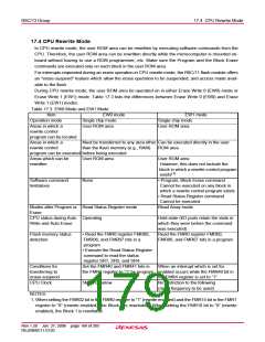
During CPU rewrite mode, the user ROM area be operated on in either Erase Write 0 (EW0) mode or
Erase Write 1 (EW1) mode. Table 17.3 lists the differences between Erase Write 0 (EW0) and Erase
Write 1 (EW1) modes.
Table 17.3 EW0 Mode and EW1 Mode
Item
EW0 mode
Single chip mode
User ROM area
EW1 mode
Single chip mode
User ROM area
Operation mode
Areas in which a
rewrite control
program can be located
Areas in which a
rewrite control
Must be transferred to any area other Can be executed directly in the user
than the flash memory (e.g., RAM)
ROM area
program can be executed before being executed
Areas which can be
rewritten
User ROM area
User ROM area
However, this does not include the
block in which a rewrite control program
(1)
exists
Software command
limitations
None
• Program, Block Erase command
Cannot be executed on any block in
which a rewrite control program exists
• Read Status Register command
Cannot be executed
Modes after Program or Read Status Register mode
Erase
Read Array mode
CPU status during Auto Operating
Write and Auto Erase
Hold state (I/O ports retain the state in
which they were before the command
was executed)
Flash memory status
detection
• Read the FMR0 register FMR00,
FMR06, and FMR07 bits in a
program
Read the FMR0 register FMR00,
FMR06, and FMR07 bits in a program
• Execute the Read Status Register
command to read the status
register SR7, SR5, and SR4.
Set the FMR40 and FMR41 bits in
the FMR4 register to “1” by program. enabled occurs while the FMR40 bit in
the FMR4 register is set to “1”.
Conditions for
transferring to
erase-suspend
CPU Clock
When an interrupt which is set for
5MHz or below
No restriction to the following
(clock frequency to be used)
NOTES:
1. When setting the FMR02 bit in the FMR0 register to “1” (rewrite enabled) and the FMR15 bit in the FMR1
register to “0” (rewrite enabled), the Block 0 is rewritable. When setting the FMR16 bit to “0” (rewrite
enabled), the Block 1 is rewritable.
Rev.1.20 Jan 27, 2006 page 168 of 205
REJ09B0111-0120

 RENESAS [ RENESAS TECHNOLOGY CORP ]