R8C/13 Group
17.4 CPU Rewrite Mode
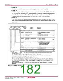
Figure 17.3 shows the FMR0 register. Figure 17.4 shows the FMR1 and FMR4 registers.
• FMR00 Bit
This bit indicates the operating status of the flash memory. The bit is “0” during programming, eras-
ing, or erase-suspend mode; otherwise, the bit is “1”.
• FMR01 Bit
The microcomputer is made ready to accept commands by setting the FMR01 bit to “1” (CPU rewrite
mode).
• FMR02 Bit
The Block1 and Block0 do not accept the Program and Block Erase commands if the FMR02 bit is
set to “0” (rewrite disabled).
The Block0 and Block1 are controlled rewriting in the FMR15 and FMR16 bits if the FMR02 bit is set
to “1” (rewrite enabled).
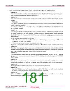
• FMSTP Bit
This bit is provided for initializing the flash memory control circuits, as well as for reducing the amount
of current consumed in the flash memory. The flash memory is disabled against access by setting
the FMSTP bit to “1”. Therefore, the FMSTP bit must be written to by a program in other than the
flash memory.
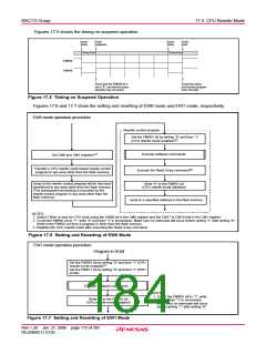
In the following cases, set the FMSTP bit to “1”:
• When flash memory access resulted in an error while erasing or programming in EW0 mode
(FMR00 bit not reset to “1” (ready))
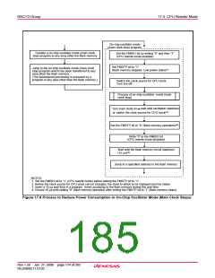
• When entering on-chip oscillator mode (main clock stop)
Figure 17.7 shows a flow chart to be followed before and after entering on-chip oscillator mode (main
clock stop).
Note that when going to stop or wait mode while the CPU rewrite mode is disabled, the FMR0
register does not need to be set because the power for the flash memory is automatically turned off
and is turned back on again after returning from stop or wait mode.
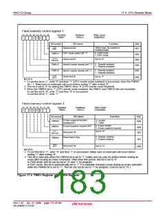
• FMR06 Bit
This is a read-only bit indicating the status of auto program operation. The bit is set to “1” when a
program error occurs; otherwise, it is cleared to “0”. For details, refer to the description of “17.4.5 full
status check”.
• FMR07 Bit
This is a read-only bit indicating the status of auto erase operation. The bit is set to “1” when an erase
error occurs; otherwise, it is set to “0”. For details, refer to the description of “17.4.5 full status check”.
• FMR11 Bit
Setting this bit to “1” (EW1 mode) places the microcomputer in EW1 mode.
• FMR15 Bit
When the FMR02 bit is set to “1” (rewrite enabled) and the FMR15 bit is set to “0” (rewrite enabled),
the Block0 accepts the program command and block erase command.
• FMR16 Bit
When the FMR02 bit is set to “1” (rewrite enabled) and the FMR16 bit is set to “0” (rewrite enabled),
the Block1 accepts the program command and block erase command.
Rev.1.20 Jan 27, 2006 page 170 of 205
REJ09B0111-0120

 RENESAS [ RENESAS TECHNOLOGY CORP ]