R8C/13 Group
17. Memory Map
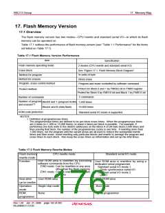
17. Flash Memory Version
17.1 Overview
The flash memory version has two modes—CPU rewrite and standard serial I/O—in which its flash
memory can be operated on.
Table 17.1 outlines the performance of flash memory version (see “Table 1.1 Performance” for the items
not listed on Table 17.1).
Table 17.1 Flash Memory Version Performance
Item
Specification
Flash memory operating mode
2 modes (CPU rewrite and standard serial I/O)
Erase block
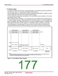
See “Figure 17.1. Flash Memory Block Diagram”
In units of byte
Method for program
Method for erasure
Program, erase control method
Block erase
Program and erase controlled by software command
Protect for Block 0 and 1 by FMR02 bit in FMR0 register
Protect for Block 0 by FMR16 bit and Block 1 by FMR16 bit
Protect method
5 commands
Number of commands
Number of program
and erasure
Block0 and 1 (program ROM)
BlockA and B (data flash)
1,000 times
(1)
10,000 times
ROM code protection
NOTES:
Standard serial I/O mode is supported.
1: Definition of program/erase times
The program/erase times are defined to be per-block erase times. When the program/erase times
are n times (n=1,000 or 10,000 times), to erase n times per block is possible. For example, if
performing one-byte write to the distinct addresses on the Block A of 2K-byte block 2,048 times and
then erasing that block, the number of the program/erase cycles is one time. if rewriting more than
1,000 times, run the program until the vacant areas are all used to reduce the substantial rewrite
times and then erase. Avoid rewriting only particular blocks and rewrite to average the program and
erase times to each block. Also keep the erase times as inrformation and set up the limit times.
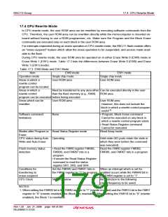
Table 17.2 Flash Memory Rewrite Modes
Flash memory
rewrite mode
Function
CPU rewrite mode
Standard serial I/O mode
User ROM area is rewritten by executing
software commands from the CPU.
EW0 mode: Can be rewritten in any area
other than the flash memory
EW1 mode: Can be rewritten in the flash
memory
User ROM area is rewritten by using a
dedicated serial programmer.
Standard serial I/O mode 1
: Clock synchronous serial I/O
Standard serial I/O mode 2
: UART
Areas which
can be rewritten
Operation
mode
User ROM area
Single chip mode
None
User ROM area
Boot mode
ROM
Serial programmer
programmer
Rev.1.20 Jan 27, 2006 page 165 of 205
REJ09B0111-0120

 RENESAS [ RENESAS TECHNOLOGY CORP ]