M37161M8/MA/MF-XXXSP/FP,M37161EFSP/FP
8.10.1 Display Position
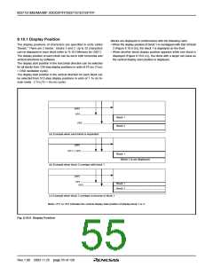
Blocks are displayed in conformance with the following rules:
• When the display position of block 1 is overlapped with that of block
2 (Figure 8.10.6 (b)), the block 1 is displayed on the front.
• When another block display position appears while one block is
displayed (Figure 8.10.6 (c)), the block with a larger set value as
the vertical display start position is displayed.
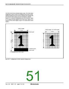
The display positions of characters are specified in units called
“blocks.” There are 2 blocks : blocks 1 and 2. Up to 32 characters
can be displayed in each block (refer to “8.10.5 Memory for OSD”).
The display position of each block can be set in both horizontal and
vertical directions by software.
The display start position in the horizontal direction can be selected
for all blocks from 128-step display positions in units of 4TOSC (TOSC
= OSD oscillation cycle).
The display start position in the vertical direction for each block can
be selected from 512-step display positions in units of 1 TH (in bi-
scan mode : 2 TH) (TH = HSYNC cycle).
(HP)
VP1
Block 1
Block 2
VP2
(a) Example when each block is separated
(HP)
VP1 = VP2
Block 1
(Block 2 is not displayed)
(b) Example when block 2 overlaps with block 1
(HP)
VP1
VP2
Block 1
Block 2
(c) Example when block 2 overlaps in process of block 1
Note: VP1 or VP2 indicates the vertical display start position of display block 1 or 2.
Fig. 8.10.6 Display Position
Rev.1.00 2003.11.25 page 55 of 128

 RENESAS [ RENESAS TECHNOLOGY CORP ]