14.1.2
Input and Output Pins
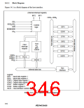
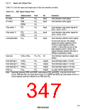
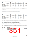
Table 14.1 lists the input and output pins of the host interface module.
Table 14.1 HIF Input/Output Pins
Name
Abbreviation
IOR
Port
P83
P84
P91
P82
I/O
Function
I/O read
I/O write*
Input
Input
Host interface read signal
Host interface write signal
IOW
EIOW
CS1
Chip select 1
Input
Input
Host interface chip select signal for
IDR1, ODR1, STR1
Chip select 2*
CS2
P85
P90
P80
Host interface chip select signal for
IDR2, ODR2, STR2
ECS2
HA0
Command/data
Input
Host interface address select signal
In host read access, this signal
selects the status registers (STR1,
STR2) or data registers (ODR1,
ODR2). In host write access to the
data registers (IDR1, IDR2), this
signal indicates whether the host is
writing a command or data.
Data bus
HDB7–HDB0
HIRQ1
P37–P30
I/O
Host interface data bus (single-chip
mode)
Host interrupt 1
P44
P43
P45
P81
Output
Output
Output
Output
Host interrupt output 1 to host
Host interrupt output 11 to host
Host interrupt output 12 to host
A20 gate control signal output
Host interrupt 11 HIRQ11
Host interrupt 12 HIRQ12
Gate A20
GA20
Note: * Selection between IOW and EIOW, and between CS2 and ECS2, is by the STAC bit in
STCR. IOW and CS2 are used when STAC is 0. EIOW and ECS2 are used when STAC is 1.
In this manual, both are referred to as IOW and CS2.
317

 RENESAS [ RENESAS TECHNOLOGY CORP ]