14.1.3
Register Configuration
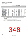
Table 14.2 lists the host interface registers.
Table 14.2 HIF Registers
R/W
Abbreviation Slave Host Value Address*3 CS1 CS2 HA0
Master Address*4
Initial Slave
Name
System control register SYSCR
R/W*1
—
—
H'09
H'F8
H'FFC4
H'FFF0
—
—
—
—
—
—
Host interface control
register
HICR
R/W
Input data register 1
IDR1
R
W
R
—
H'FFF4
H'FFF5
H'FFF6
H'FFFC
H'FFFD
H'FFFE
H'FFC3
0
1
0/1*5
0
Output data register 1 ODR1
R/W
R/(W)*2
R
—
0
1
Status register 1
STR1
IDR2
R
H'00
—
0
1
1
0/1*5
Input data register 2
W
R
1
0
Output data register 2 ODR2
R/W
R/(W)*2
R/W
—
1
0
0
Status register 2
STR2
STCR
R
H'00
H'00
1
0
1
Serial/timer control
register
—
—
—
—
Notes: *1 Bit 3 is a read-only bit.
*2 The user-defined bits (bits 7 to 4 and 2) are read/write accessible from the slave
processor.
*3 Address when accessed from the slave processor.
*4 Pin inputs used in access from the host processor.
*5 The HA0 input discriminates between writing of commands and data.
318

 RENESAS [ RENESAS TECHNOLOGY CORP ]