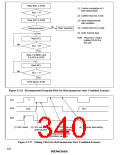
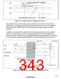
SCL high level duration maintained
SCL
SDA
VIH
SCL low level detected
IRIC
SCL determined to be low level
IRIC cleared
Figure 13.20 IRIC Flag Clear Timing when WAIT = 1
Note that the clock may not be output properly during the next master send if receive data
(ICDR data) is read during the time between when the instruction to issue a stop condition is
executed (writing 0 to BBSY and SCP in ISSR) and when the stop condition is actually
generated.
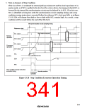
In addition, overwriting of IIC control bits in order to change the send or receive operation
mode or to change settings, such as for example clearing the MST bit after completion of
master send or receive, should always be performed during the period indicated as (a) in Figure
13.21 below (after confirming that the BBSY bit in the ICCR register has been cleared to 0).
Stop condition
Start condition
(a)
Bit 0
8
A
9
SDA
SCL
Internal clock
BBSY bit
Master receive mode
ICDR read F
prohibited duration
Execution of issue
stop condition instruction
Stop condition generated
(BBSY = 0 read)
Start condition issued
(BBSY = 0 and SCP = 0 written)
Figure 13.21 Precautions when Reading Master Receive Data
313

 RENESAS [ RENESAS TECHNOLOGY CORP ]