Bit 2—Input Buffer Full Interrupt Enable 2 (IBFIE2): Enables or disables the IBF2 interrupt
to the slave CPU.
Bit 2: IBFIE2
Description
0
1
IDR2 input buffer full interrupt is disabled
IDR2 input buffer full interrupt is enabled
(Initial value)
Bit 1— Input Buffer Full Interrupt Enable 1 (IBFIE1): Enables or disables the IBF1 interrupt
to the slave CPU.
Bit 1: IBFIE1
Description
0
1
IDR1 input buffer full interrupt is disabled
IDR1 input buffer full interrupt is enabled
(Initial value)
Bit 0—Fast Gate A20 Enable (FGA20E): Enables or disables the fast A20 gate function. When the
fast A20 gate is disabled, a regular-speed A20 gate signal can be implemented by using software to
manipulate the P81 output.
Bit 0: FGA20E
Description
0
1
Disables fast A20 gate function
Enables fast A20 gate function
(Initial value)
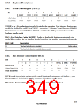
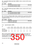
14.2.3
Input Data Register 1 (IDR1)
Bit
7
IDR7
—
6
IDR6
—
5
IDR5
—
4
IDR4
—
3
IDR3
—
2
IDR2
—
1
IDR1
—
0
IDR0
—
Initial value
Slave Read/Write
Host Read/Write
R
R
R
R
R
R
R
R
W
W
W
W
W
W
W
W
IDR1 is an 8-bit read-only register to the slave processor, and an 8-bit write-only register to the
host processor. When CS1 is low, information on the host data bus is written into IDR1 at the
rising edge of IOW. The HA0 state is also latched into the C/D bit in STR1 to indicate whether the
written information is a command or data.
The initial values of IDR1 after a reset or standby are undetermined.
320

 RENESAS [ RENESAS TECHNOLOGY CORP ]