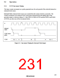
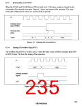
9.3.3
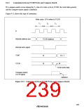
External Reset of TCNT
When the CCLR1 and CCLR0 bits in TCR are both set to 1, the timer counter is cleared on the
rising edge of an external reset input. Figure 9.7 shows the timing of this operation. The timer
reset pulse width must be at least 1.5 system clock (ø) periods.
ø
External reset
input (TMRI)
Internal clear
pulse
TCNT
N – 1
Figure 9.7 Timing of External Reset
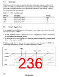
Setting of Overflow Flag (OVF)
N
H'00
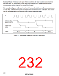
9.3.4
The overflow flag (OVF) in TCSR is set to 1 when the timer count overflows (changes from H'FF
to H'00). Figure 9.8 shows the timing of this operation.
ø
TCNT
H'FF
H'00
Internal overflow
signal
OVF
Figure 9.8 Setting of Overflow Flag (OVF)
205

 RENESAS [ RENESAS TECHNOLOGY CORP ]