Section 22 Electrical Characteristics
22.3.7
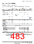
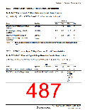
Power-Supply-Voltage Detection Circuit Characteristics
Table 22.19 Power-Supply-Voltage Detection Circuit Characteristics
VSS = 0.0 V, Ta = -20 to +75°C/-40 to +85°C, unless otherwise indicated.
Values
Typ.
Item
Symbol
Min.
Max.
Unit
Power-supply falling detection
voltage
Vint (D)
2.8
2.9
3.05
V
Power-supply rising detection
voltage
Vint (U)
2.9
3.0
3.15
V
Reset detection voltage 1*
Vreset1
VLVDRmin
—
2.3
—
2.6
—
V
V
Lower-limit voltage of LVDR
operation
1.0
Note:
*
This voltage should be used when the falling and rising voltage detection function is
used.
22.3.8
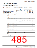
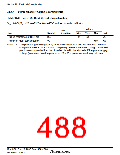
LVDI External Input Voltage Detection Circuit Characteristics
Table 22.20 LVDI External Input Voltage Detection Circuit Characteristics
Vcc = 3.0 to 3.6 V, AVcc = 3.0 to 3.6 V, VSS = 0.0 V, Ta = -20 to +75°C/-40 to +85°C
Values
Test
Item
Symbol
Condition
Min.
Typ.
1.15
Max.
Unit
V
ExtD/ExtU input detection voltage
ExtD/ExtU input voltage range
Vexd
0.95
1.35
VextD/VextU VextD > VextU −0.3
Lower
V
voltage
of AVcc
+ 0.3 or
Vcc
+
0.3
Rev. 3.00 Sep. 10, 2007 Page 453 of 528
REJ09B0216-0300

 RENESAS [ RENESAS TECHNOLOGY CORP ]