6.4
INTC Operation
6.4.1
Interrupt Sequence
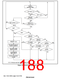
The sequence of interrupt operations is described below. Figure 6.3 is a flowchart of the
operations.
1. The interrupt request sources send interrupt request signals to the interrupt controller.
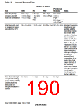
2. The interrupt controller selects the highest-priority interrupt from the interrupt requests sent,
following the priority levels set in interrupt priority registers A to E (IPRA to IPRE). Lower
priority interrupts are held pending. If two of these interrupts have the same priority level or if
multiple interrupts occur within a single module, the interrupt with the highest default priority
or the highest priority within its IPR setting unit (as indicated in tables 6.4 and 6.5) is selected.
3. The priority level of the interrupt selected by the interrupt controller is compared with the
interrupt mask bits (I3–I0) in the status register (SR) of the CPU. If the request priority level is
higher than the level in bits I3–I0, the interrupt controller accepts the interrupt and sends an
interrupt request signal to the CPU. When the interrupt controller receives an interrupt, a low
level is output from the IRQOUT pin.
4. Detection timing: The INTC operates, and notifies the CPU of interrupt requests, in
synchronization with the peripheral clock (Pφ). The CPU receives an interrupt at a break in
instructions.
5. The interrupt source code is set in the interrupt event registers (INTEVT and INTEVT2).
6. The status register (SR) and program counter (PC) are saved to SSR and SPC, respectively.
7. The block bit (BL), mode bit (MD), and register bank bit (RB) in SR are set to 1.
8. The CPU jumps to the start address of the interrupt handler (the sum of the value set in the
vector base register (VBR) and H'00000600). This jump is not a delayed branch. The interrupt
handler may branch with the INTEVT and INTEVT2 register value as its offset in order to
identify the interrupt source. This enables it to branch to the handling routine for the individual
interrupt source.
Notes: 1. The interrupt mask bits (I3–I0) in the status register (SR) are not changed by
acceptance of an interrupt in the SH7709S.
2. IRQOUT outputs a low level until the interrupt request is cleared. However, if the
interrupt source is masked by an interrupt mask bit, the IRQOUT pin returns to the
high level. The level is output without regard to the BL bit.
3. The interrupt source flag should be cleared in the interrupt handler. To ensure that an
interrupt request that should have been cleared is not inadvertently accepted again, read
the interrupt source flag after it has been cleared, then wait for the interval shown in
table 6.8 (Time for priority decision and SR mask bit comparison) before clearing the
BL bit or executing an RTE instruction.
Rev. 5.00, 09/03, page 143 of 760

 RENESAS [ RENESAS TECHNOLOGY CORP ]