6.1.2
Block Diagram
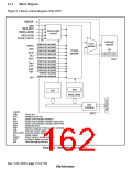
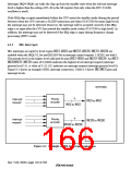
Figure 6.1 shows a block diagram of the INTC.
IRQOUT
NMI
IRL3–IRL0
4
4
Input/output
control
IRLS3–IRLS0
IRQ0–IRQ5
6
PINT0–PINT15
16
Interrupt
request
Com-
parator
(Interrupt request)
(Interrupt request)
(Interrupt request)
(Interrupt request)
DMAC
IrDA
SR
Priority
identifier
SCIF
SCI
3
2 1 0
(Interrupt request)
ADC
CPU
(Interrupt request)
(Interrupt request)
(Interrupt request)
(Interrupt request/
refresh request)
TMU
RTC
WDT
REF
(Interrupt request)
UDI
IPR
ICR
IPRA–IPRE
Bus
interface
Legend
INTC
TMU
RTC
SCI
IrDA
SCIF
WDT
REF
ICR
: Timer unit
: Realtime clock unit
: Serial communication interface
: Serial communication interface (with IrDA)
: Serial communication interface (with FIFO)
: Watchdog timer
: Refresh requests in the bus state controller
: Interrupt control register
IPRA–IPRE : Interrupt priority registers A−E
SR
: Status register
DMAC
ADC
UDI
: Direct memory access controller
: Analog-to-digital converter
: User-debugging interface
Figure 6.1 Block Diagram of INTC
Rev. 5.00, 09/03, page 118 of 760

 RENESAS [ RENESAS TECHNOLOGY CORP ]