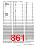
21.3.4
Boundary Scan (EXTEST, SAMPLE/PRELOAD, BYPASS) (SH7750R Only)
In the SH7750R, setting a command from the H-UDI in SDIR can place the H-UDI pins in the
boundary scan mode that conforms to the JTAG standard. However, the following limitations
apply.
1. Boundary scan does not cover clock-related signals (EXTAL, EXTAL2, XTAL, XTAL2, and
CKIO).
2. Boundary scan does not cover reset-related signals (5(6(7, CA)
3. Boundary scan does not cover H-UDI-related signals (TCK, TDI, TDO, TMS, 7567).
4. With EXTEST, assert the 5(6(7 pin (low), and assert the CA pin (high). With
SAMPLE/PRELOAD, assert the CA pin (high).
5. To perform boundary scan, supply a clock to the EXTAL pin, and wait for the power-on
oscillation settling time to elapse before starting boundary scan. The frequency range of the
input clock is from 1 to 33.3 MHz.
Note that after the power-on oscillation settling time has elapsed, a clock does not need to be
supplied to the EXTAL pin any longer.
For details on the power-on oscillation settling time, see section 22, Electrical Characteristics.
6. In BYPASS mode of the SH7750 or SH7750S, the bypass register (SPDBPR) is not initialized
in the Capture-DR state.
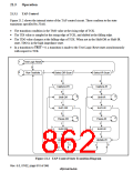
21.4
Usage Notes
1. SDIR Command
Once an SDIR command has been set, it remains unchanged until initialization by asserting
7567 or placing the TAP in the Test-Logic-Reset state, or until another command (other than
an H-UDI interrupt command) is written from the H-UDI.
2. SDIR Commands in Sleep Mode
Sleep mode is cleared by an H-UDI interrupt or H-UDI reset, and these exception requests are
accepted in this mode. In standby mode, neither an H-UDI interrupt nor an H-UDI reset is
accepted.
3. In standby mode, the H-UDI function cannot be used. Furthermore, TCK must be retained at a
high level when entering the standby mode in order to retain the TAP state before and after
standby mode.
4. The H-UDI is used for emulator connection. Therefore, H-UDI functions cannot be used when
an emulator is used.
5. The H-UDI pins of the SH7750 and SH7750S must not be connected to a boundary-scan signal
loop on the board.
Rev. 6.0, 07/02, page 812 of 986

 RENESAS [ RENESAS TECHNOLOGY CORP ]