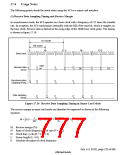
(3) Standby Mode and Clock
When switching between smart card interface mode and standby mode, the following procedures
should be used to maintain the clock duty cycle.
Switching from Smart Card Interface Mode to Standby Mode:
1. Set the SBP1IO and SBP1DT bits in SCSPTR1 to the values for the fixed output state in
standby mode.
2. Write 0 to the TE and RE bits in the serial control register (SCSCR1) to stop transmit/receive
operations. At the same time, set the CKE1 bit to the value for the fixed output state in standby
mode.
3. Write 0 to the CKE0 bit in SCSCR1 to stop the clock.
4. Wait for one serial clock cycle. During this period, the duty cycle is preserved and clock output
is fixed at the specified level.
5. Write H'00 to the serial mode register (SCSMR1) and smart card mode register (SCSMR1).
6. Make the transition to the standby state.
Returning from Standby Mode to Smart Card Interface Mode:
7. Clear the standby state.
8. Set the CKE1 bit in SCSCR1 to the value for the fixed output state at the start of standby (the
current SCK pin state).
9. Set smart card interface mode and output the clock. Clock signal generation is started with the
normal duty cycle.
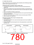
Standby mode
Normal operation
Normal operation
1 2 3
4
5 6
7
8 9
Figure 17.13 Procedure for Stopping and Restarting the Clock
Rev. 6.0, 07/02, page 728 of 986

 RENESAS [ RENESAS TECHNOLOGY CORP ]