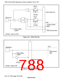
18.1.2 Block Diagrams
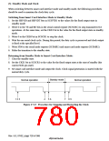
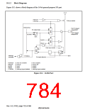
Figure 18.1 shows a block diagram of the 16-bit general-purpose I/O port.
PBnPUP
PORTEN
Pull-up resistor
Internal bus
Port 15 (input/
output)/D47
to
Port 0 (input/
output)/D32
0
Dn output data
1
D
Q
C
PDTRW
BCK
0
1
DnDIR
PBnIO
Data input strobe
0
1
C
D
Q
Interrupt
controller
BCK
PTIRENn
Dn input data
PORTEN
PBnPuP
DnDIR
0: Port not available
1: Port available
1: Pull-up off
1: Output
0: Pull-up
0: Input
0: Input
PBnIO
1: Output
PTIRENn 0: Interrupt input disabled 1: Interrupt input enabled
Figure 18.1 16-Bit Port
Rev. 6.0, 07/02, page 732 of 986

 RENESAS [ RENESAS TECHNOLOGY CORP ]