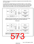
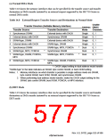
(a) Normal DMA Mode
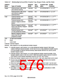
Table 14.8 shows the memory interfaces that can be specified for the transfer source and transfer
destination in DMA transfer initiated by an external request supported by the SH7750 Series in
normal DMA mode.
Table 14.8 External Request Transfer Sources and Destinations in Normal Mode
Usable
Transfer Direction (Settable Memory Interface)
Address DMAC
Transfer Source
Transfer Destination
External device with DACK
Synchronous DRAM
Mode
Single
Single
Single
Single
Dual
Channels
1
2
3
4
5
6
7
Synchronous DRAM
0, 1
External device with DACK
SRAM-type, DRAM
0, 1
External device with DACK
SRAM-type, DRAM
0, 1
External device with DACK
Synchronous DRAM
0, 1
SRAM-type, MPX, PCMCIA
Synchronous DRAM
*
*
0, 1
SRAM-type, MPX, PCMCIA
*
*
Dual
0, 1
SRAM-type, DRAM, PCMCIA,
MPX
SRAM-type, MPX, PCMCIA
Dual
0, 1
8
SRAM-type, MPX, PCMCIA
SRAM-type, DRAM, PCMCIA,
MPX
Dual
0, 1
*: DACK output setting in dual address mode transfer
"SRAM-type" in the table indicates an SRAM, byte control SRAM, or burst ROM setting.
Notes: 1. Memory interfaces on which transfer is possible in single address mode are SRAM,
byte control SRAM, burst ROM, DRAM, and synchronous DRAM.
2. When performing dual address mode transfer, make the DACK output setting for the
SRAM, byte control SRAM, burst ROM, PCMCIA, or MPX interface.
(b) DDT Mode
Table 14.9 shows the memory interfaces that can be specified for the transfer source and transfer
destination in DMA transfer initiated by an external request supported by the SH7750 Series in
DDT mode.
Rev. 6.0, 07/02, page 525 of 986

 RENESAS [ RENESAS TECHNOLOGY CORP ]