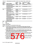
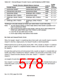
Table 14.9 External Request Transfer Sources and Destinations in DDT Mode
Usable
Address DMAC
Transfer Direction (Settable Memory Interface)
Transfer Source
Transfer Destination
Mode
Single
Single
Dual
Channels
1
*
1
2
3
4
5
Synchronous DRAM
External device with DACK
Synchronous DRAM
0, 1, 2, 3
0, 1, 2, 3
0, 1, 2, 3
0, 1, 2, 3
0, 1, 2, 3
External device with DACK
Synchronous DRAM
2
2
*
*
SRAM-type, MPX, PCMCIA
Synchronous DRAM
2
2
*
*
SRAM-type, MPX, PCMCIA
Dual
SRAM-type, DRAM, PCMCIA,
MPX
SRAM-type, MPX, PCMCIA
Dual
6
SRAM-type, MPX, PCMCIA
SRAM-type, DRAM, PCMCIA,
MPX
Dual
0, 1, 2, 3
"SRAM-type" in the table indicates an SRAM, byte control SRAM, or burst ROM setting.
Notes: 1. The only memory interface on which single address mode transfer is possible in DDT
mode is synchronous DRAM.
2. When performing dual address mode transfer, make the DACK output setting for the
SRAM, byte control SRAM, burst ROM, PCMCIA, or MPX interface.
*1 In SH7750, the bus width must be 64 bits
*2 DACK output setting in dual address mode transfer
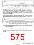
Bus Mode and Channel Priority Order
When, for example, channel 1 is transferring data in burst mode, and a transfer request is issued to
channel 0, which has a higher priority, the channel 0 transfer is started immediately.
If fixed mode has been set for the priority levels (CH0 > CH1), transfer on channel 1 is continued
after transfer on channel 0 is completely finished, whether cycle steal mode or burst mode is set
for channel 0.
If round robin mode has been set for the priority levels, transfer on channel 1 is restarted after one
transfer unit of data is transferred on channel 0, whether cycle steal mode or burst mode is set for
channel 0. Channel execution alternates in the order: channel 1 → channel 0 → channel 1 →
channel 0.
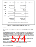
An example of round robin mode operation is shown in figure 14.11.
Since channel 1 is in burst mode (in the case of edge sensing) regardless of whether fixed mode or
round robin mode is set for the priority order, the bus is not released to the CPU until channel 1
transfer ends.
Rev. 6.0, 07/02, page 526 of 986

 RENESAS [ RENESAS TECHNOLOGY CORP ]