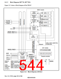
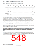
14.1.2 Block Diagram (SH7750, SH7750S)
Figure 14.1 shows a block diagram of the DMAC.
DMAC module
SARn
Count
control
Register
control
DARn
DMATCRn
CHCRn
Activation
control
On-chip
peripheral
module
DMAOR
Request
priority
control
TMU
SCI, SCIF
DACK0, DACK1
DRAK0, DRAK1
Bus
interface
4
SAR0, DAR0, DMATCR0,
CHCR0 only
Request
DDT module
,
DTR command buffer
32B data
buffer
CH0 CH1 CH2 CH3
Request controller
DBREQ
D[63:0]
ID[1:0]
External bus
Bus state
controller
DDTMODE
BAVL
DDTD
48 bits
id[1:0]
DMAOR:
SARn:
DMAC operation register
DMAC source address
register
tdack
DARn:
DMAC destination address register
DMATCRn: DMAC transfer count register
CHCRn:
DMAC channel control register
(n: 0 to 3)
Figure 14.1 Block Diagram of DMAC
Rev. 6.0, 07/02, page 492 of 986

 RENESAS [ RENESAS TECHNOLOGY CORP ]