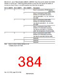
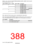
13.2.2 Bus Control Register 2 (BCR2)
Bus control register 2 (BCR2) is a 16-bit readable/writable register that specifies the bus width for
each area, and whether a 16-bit port is used.
BCR2 is initialized to H'3FFC by a power-on reset, but is not initialized by a manual reset or in
standby mode. External memory space other than area 0 should not be accessed until register
initialization is completed.
Bit:
15
14
13
12
11
10
9
8
Bit name: A0SZ1 A0SZ0 A6SZ1 A6SZ0 A5SZ1 A5SZ0 A4SZ1 A4SZ0
Initial value:
R/W:
0/1*
0/1*
1
1
1
1
1
1
R
R
R/W
R/W
R/W
R/W
R/W
R/W
Bit:
7
6
5
4
3
2
1
—
0
0
PORTEN
0
Bit name: A3SZ1 A3SZ0 A2SZ1 A2SZ0 A1SZ1 A0SZ0
Initial value:
R/W:
1
1
1
1
1
1
R/W
R/W
R/W
R/W
R/W
R/W
—
R/W
Note: * These bits sample the values of the external pins that specify the area 0 bus size.
Bits 15 and 14—Area 0 Bus Width (A0SZ1, A0SZ0): These bits sample the external pins, MD4
and MD3 that specify the bus size in a power-on reset by the 5(6(7 pin. They are read-only bits.
Bit 15
A0SZ1
0
Bit 14
A0SZ0
Description
0
1
0
1
Bus width is 64 bits
Bus width is 8 bits
Bus width is 16 bits
Bus width is 32 bits
1
Rev. 6.0, 07/02, page 335 of 986

 RENESAS [ RENESAS TECHNOLOGY CORP ]