13.2
Register Descriptions
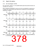
13.2.1 Bus Control Register 1 (BCR1)
Bus control register 1 (BCR1) is a 32-bit readable/writable register that specifies the function, bus
cycle status, etc., of each area.
BCR1 is initialized to H'00000000 by a power-on reset, but is not initialized by a manual reset or
in standby mode. External memory space other than area 0 should not be accessed until register
initialization is completed.
Bit:
31
30
29
28
—
0
27
—
0
26
DPUP
0
25
IPUP
0
24
OPUP
0
2
*
ENDIAN MASTER A0MPX
1
1
1
*
*
*
0/1
0/1
0/1
Initial value:
R/W:
R
R
R
R
R
R
R/W
R/W
Bit:
23
—
0
22
—
0
21
20
19
18
17
16
2
*
A1MBC A4MBC BREQEN PSHR MEMMPX DMABST
Initial value:
R/W:
0
0
0
0
0
0
R
R
R/W
R/W
R/W
R/W
R/W
R
Bit:
15
14
13
A0BST2
0
12
A0BST1
0
11
A0BST0
0
10
A5BST2
0
9
A5BST1
0
8
HIZMEM HIZCNT
A5BST0
0
Initial value:
R/W:
0
0
R/W
R/W
R/W
R/W
R/W
R/W
R/W
R/W
Bit:
7
A6BST2
0
6
A6BST1
0
5
4
3
2
1
—
0
0
A56PCM
0
A6BST0 DRAMTP2 DRAMTP1 DRAMTP0
Initial value:
R/W:
0
0
0
0
R/W
R/W
R/W
R/W
R/W
R/W
R
R/W
Notes: *1 These bits sample external pin values in a power-on reset by means of the 5(6(7 pin.
*2 SH7750R only.
Rev. 6.0, 07/02, page 326 of 986

 RENESAS [ RENESAS TECHNOLOGY CORP ]