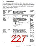
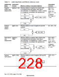
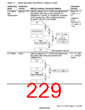
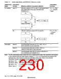
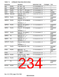
Table 7.1 Addressing Modes and Effective Addresses (cont)
Addressing Instruction
Calculation
Formula
Mode
Format
Effective Address Calculation Method
PC-relative
disp:12
Effective address is PC+4 with 12-bit displacement PC + 4 + disp
disp added after being sign-extended and
multiplied by 2.
× 2 → Branch-
Target
PC
+
4
+
PC + 4 + disp × 2
disp
(sign-extended)
×
2
Rn
Effective address is sum of PC+4 and Rn.
PC + 4 + Rn
→ Branch-
Target
PC
+
+
PC + 4 + Rn
4
Rn
Immediate
#imm:8
#imm:8
#imm:8
8-bit immediate data imm of TST, AND, OR, or
XOR instruction is zero-extended.
—
—
—
8-bit immediate data imm of MOV, ADD, or
CMP/EQ instruction is sign-extended.
8-bit immediate data imm of TRAPA instruction is
zero-extended and multiplied by 4.
Note: For the addressing modes below that use a displacement (disp), the assembler descriptions
in this manual show the value before scaling (×1, ×2, or ×4) is performed according to the
operand size. This is done to clarify the operation of the chip. Refer to the relevant
assembler notation rules for the actual assembler descriptions.
@ (disp:4, Rn) ; Register indirect with displacement
@ (disp:8, GBR) ; GBR indirect with displacement
@ (disp:8, PC) ; PC-relative with displacement
disp:8, disp:12 ; PC-relative
Rev. 6.0, 07/02, page 178 of 986

 RENESAS [ RENESAS TECHNOLOGY CORP ]