PULSE OUTPUT PORT MODE
9.3 Block description of pulse output port 1
9.3.5 Pin P4OUTCUT (pulse-output-cutoff signal input pin)
When a falling edge is input to pin P4OUTCUT, the waveform output control bit 1 (bit 7 at address A016
)
becomes “0” and the pulse output pins enter the floating state. (In other words, pulse output becomes
disabled.) The pulse output pins where pulse output is to be inactive depend on the pulse output mode.
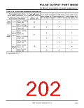
• Pulse mode 0: RTP2
• Pulse mode 1: RTP2
0
to RTP2
to RTP2
3
0
3
, RTP3
0
, RTP3
1
When restarting pulse output after the pulse output becomes inactive, be sure to return the input level at
pin P4OUTCUT to “H” level; and then, be sure to set the waveform output control bit 1 to “1.” When the input
level at pin P4OUTCUT is “L” level, the waveform output control bit 1 cannot be “1.”
Also, at this time, bits 0 through 7 of the port P4 direction register (address C16) become “00000000
(Refer to section “5.2.3 Pin P4OUTCUT/INT .”) Therefore, if it is necessary to switch port pins P6 through
P6 to port output pins, be sure to do as follows:
➀ Return the input level at pin P4OUTCUT to “H” level.
2
.”
0
0
7
➀ Write data to the port P4 register (address A16)’s bits, corresponding to the port P4 pins which will
output data.
➀ Set the port P4 direction register’s bits, corresponding to the port P4 pins in ➀, to “1” in order to set
these port pins to the output mode.
When the input level at pin P4OUTCUT is “L” level, no bit of the port P4 direction register can be “1.”
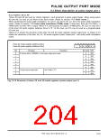
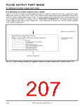
Figure 9.3.7 shows the relationship between the P4OUTCUT input, waveform output control bit 1, and pulse
output pin.
Note that, when not making the pulse output inactive by using pin P4OUTCUT, be sure to connect pin
P4OUTCUT to Vcc via a resistor.
Selection of pulse output port mode
(selected by bit s 3 to 0 at address A016
)
➀
P4OUTCUT input
➀
➀
Waveform output control bit 1
(bit 7 at address A016)
➀
Programmable
I/O port
Pulse output
Pulse output
Pulse output pin
Floating
Floating
➀ When the pulse output port mode is selected, the pulse outpit pins become floating.
➀ The pulse is output by writing of “1” with the input level at pin P4OUTCUT = “H.”
➀ When a falling edge is input to pin P4OUTCUT, this bit becomes “0.”
Fig. 9.3.7 Relationship between P4OUTCUT input, waveform output control bit 1, and pulse output pin
7905 Group User’s Manual Rev.1.0
9-25

 RENESAS [ RENESAS TECHNOLOGY CORP ]