PULSE OUTPUT PORT MODE
9.4 Setting of pulse output port mode
9.4 Setting of pulse output port mode
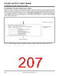
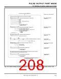
Figures 9.4.1 to 9.4.5 show an initial setting example for registers relevant to the pulse output port mode,
where pins RTP0
0
to RTP0
3
, RTP1
0
, RTP1 are used as pulse output pins and an underflow of timer A0 is
1
used as a pulse output trigger (pulse mode 1 of pulse output port 0). Note that when using interrupts, set
up to enable the interrupts. For details, refer to “CHAPTER 6. INTERRUPTS.” The above setting example
is also applied to the case of pulse output port 1. Each right side of Figures 9.4.1 to 9.4.5 shows registers
used in pulse output port 1.
Registers used in pulse output port 1
Selecting pulse output mode and Selecting each function
b7
b0
Waveform output mode register (Address A616
)
Pulse output control register
(Address A016
0
0
1
0
0
1
)
Pulse mode 1
Pulse width modulation timer select bits
See Table 9.2.2.
Waveform output control bit 0
RTP12, RTP13: pulse output is disabled.
Waveform output control bit 1
Pulse output is disabled.
✽ Pulse output pins are floating until the pulse output becomes enabled.
Continued on Figure 9.4.2.
Fig. 9.4.1 Initial setting example for registers relevant to pulse output port 0 (pulse mode 1) (1)
7905 Group User’s Manual Rev.1.0
9-26

 RENESAS [ RENESAS TECHNOLOGY CORP ]