TIMER A
7.3 Timer mode
7.3.3 Select function
The following describes the gate and pulse output functions.
(1) Gate function
The gate function is selected by setting the gate function select bits (bits 4 and 3 at addresses 5616
” or “11 .” The gate function makes it possible to start or stop counting
to 5A16, D616 to DA16) to “10
2
2
depending on the TAiIN pin’s input signal. Table 7.3.2 lists the count valid levels.
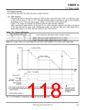
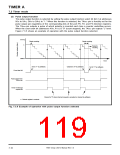
Figure 7.3.4 shows an example of operation with the gate function selected.
When selecting the gate function, set the port P6, P2, and P4 direction registers’ bits which correspond
to the TAiIN pins for the input mode. Additionally, make sure that the TAiIN pin’s input signal has a
pulse width equal to or more than two cycles of the count source.
Table 7.3.2 Count valid levels
Gate function select bits
Count valid level (Duration while counter counts)
b4
1
b3
0
While TAiIN pin’s input signal level is at “L” level
While TAiIN pin’s input signal level is at “H” level
1
1
Note: The counter does not count while the TAiIN pin’s input signal is not at the count valid level.
FFFF16
n
➀ Starts counting.
➀ Stops counting.
000016
Time
Set to “1” by software.
Count start bit
Count valid
level
Invalid level
TAiIN pin’s
input signal
Timer Ai interrupt
request bit
➀ The counter counts while the count start bit = “1” and the TAiIN pin’s input signal is at the count valid level.
➀ The counter stops counting while the TAiIN pin’s input signal is not at the count valid level, and the counter
value is retained.
Cleared to “0” when
interrupt request is
accepted or cleared
by software.
n : Reload register’s contents
Fig. 7.3.4 Example of operation with gate function selected
7905 Group User’s Manual Rev.1.0
7-15

 RENESAS [ RENESAS TECHNOLOGY CORP ]