TIMER A
7.2 Block description
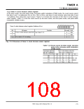
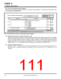
7.2.4 Timer Ai mode register
Figure 7.2.4 shows the structure of the timer Ai mode register. The operating mode select bits are used
to select the operating mode of timer Ai. Bits 2 to 7 have different functions according to the operating
mode. These bits are described in the paragraph of each operating mode.
b7 b6 b5 b4 b3 b2 b1 b0
Timer Ai mode register (i = 0 to 4) (Addresses 5616 to 5A16)
(i = 5 to 9) (Addresses D616 to DA16)
Function
Bit
0
Bit name
At reset R/W
b1 b0
Operating mode select bits
0
RW
0 0 : Timer mode
0 1 : Event counter mode
1 0 : One-shot pulse mode
1 1 : Pulse width modulation (PWM) mode
1
0
RW
(Note)
These bits have different functions according to the operating mode.
2
3
4
5
6
7
0
0
0
0
0
0
RW
RW
RW
RW
RW
RW
Fig. 7.2.4 Structure of timer Ai mode register
7905 Group User’s Manual Rev.1.0
7-7

 RENESAS [ RENESAS TECHNOLOGY CORP ]