PRODUCT SPECIFICATION
RC5041
When designing the external current sense circuitry, pay
Selecting the Inductor
careful attention to the output limitations during normal
operation and during a fault condition. If the short circuit
protection threshold current is set too low, the DC-DC con-
verter may not be able to continuously deliver the maximum
CPU load current. If the threshold level is too high, the out-
put driver may not be disabled at a safe limit and the result-
ing power dissipation within the MOSFET(s) may rise to
destructive levels.
The inductor is one of the most critical components to be
selected in the DC-DC converter application.. The critical
parameters are inductance (L), maximum DC current (Io) and
the coil resistance (R1). The inductor core material is a cru-
cial factor in determining the amount of current the inductor
will be able to withstand. As with all engineering designs,
tradeoffs exist between various types of core materials. In
general, Ferrites are popular due to their low cost, low EMI
properties and high frequency (>500KHz) characteristics.
Molypermalloy powder (MPP) materials exhibit good satura-
tion characteristics, low EMI and low hysteresis losses; how-
ever, they tend to be expensive and more effectively utilized
at operating frequencies below 400KHz. Another critical
parameter is the DC winding resistance of the inductor. This
value should typically be reduced as much as possible, as the
power loss in the DC resistance will degrade the efficiency of
The design equation used to set the short circuit threshold
limit is as follows:
Vth
-------
, where: ISC = Output short circuit current
RSENSE
=
ISC
(IPK – Imin
)
ISC ≥ Iinductor = ILoad, max + -----------------------------
2
the converter by the relationship: P
LOSS
= I 2 x R1. The
O
Where I and I
are peak ripple current and
= maximum output load current.
pk min
load, max
value of the inductor is a function of the oscillator duty cycle
I
(T ) and the maximum inductor current (I ). I can be
ON
PK PK
calculated from the relationship:
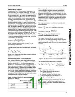
The designer must also take into account the current
(I –I ), or the ripple current flowing through the induc-
PK min
VIN – VSW – VD
-----------------------------------------
TON
IPK = IMIN
+
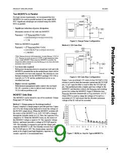
tor under normal operation. Figure 8 illustrates the inductor
current waveform for the RC5041 DC-DC converter at maxi-
mum load.
L
Where T
ON
is the maximum duty cycle and V is the
D
forward voltage of diode DS1.
Ipk
Then the inductor value can be calculated using the relation-
ship:
I
(Ipk-imin)/2
Imin
VIN – VSW – VO
-----------------------------------------
ILOAD
t
L =
TON
I
PK – IMIN
Where V
(R
x I ) is the drain-to-source voltage of
O
SW DSON
TON
TOFF
M1 when it is switched on.
T=1/f s
65-5041-10
Implementing Short Circuit Protection
Figure 8. DC-DC Converter Inductor Current Waveform
Intel currently requires all power supply manufacturers to
provide continuous protection against short circuit conditions
that may damage the CPU. To address this requirement,
Raytheon has implemented a current sense methodology to
disable the output drive signal to the MOSFET(s) when an
over current condition is detected. The voltage drop created
by the output current flowing across a sense resistor is pre-
sented to one terminal of an internal comparator with hysteri-
sis. The other comparator terminal has the threshold voltage,
nominally of 120mV. Table 4 states the limits for the compar-
ator threshold of the Switching Regulator.
The calculation of this ripple current is as follows:
(VIN – VSW – VOUT
----------------------------------------------------- ----------------------------------------------
T
)
(VOUT + VD)
(Ipk – Imin
)
--------------------------- =
2
×
L
(VIN – VSW + VD)
where:
• V = input voltage to Converter
in
• V
SW
= voltage across Switcher (MOSFET)
= I x R
LOAD
DS(ON)
• V = Forward Voltage of the Schottky diode
D
• T = the switching period of the converter = 1/fS,
where f = switching frequency.
S
Table 4. RC5041 Short Circuit Comparator
Threshold Voltage
For an input voltage of 5V, an output voltage of 3.3V, an
inductor value of 1.3µH and a switching frequency of
Short Circuit Comparator
V
(mV)
threshold
650KHz (using C =39pF), the inductor current can be
EXT
calculated as follows:
Typical
Minimum
Maximum
120
100
140
11

 RAYTHEON [ RAYTHEON COMPANY ]