PRODUCT SPECIFICATION
RC5041
The ESR rating of a capacitor is a difficult number to
RC5041 Short Circuit Current Characteristics
quantify. ESR or Equivalent Series Resistance, is defined as
the resonant impedance of the capacitor. Since the capacitor
is actually a complex impedance device having resistance,
inductance and capacitance, it is quite natural for this device
to have a resonant frequency. As a rule, the lower the ESR,
the better suited the capacitor is for use in switching power
supply applications. Many capacitor manufacturers do not
supply ESR data. A useful estimate of the ESR can be
obtained using the following equation:
The RC5041 has a short circuit current characteristic
that includes a hysteresis function that prevents the DC-DC
converter from oscillating in the event of a short circuit.
A typical V-I characteristic of the DC-DC converter output is
presented in the Operating Conditions table. The converter
performs with a normal load regulation characteristic until
the voltage across the resistor reaches the internal short cir-
cuit threshold of 120mV. At this point, the internal compara-
tor trips and sends a signal to the controller to turn off the
gate drive to the power MOSFET. This causes a drastic
reduction in the output voltage as the load regulation col-
lapses into the short circuit mode of control. The output volt-
age will not return to the normal load characteristic until the
output short circuit current is reduced to within the safe
range for the DC-DC converter.
DF
ESR = ------------
2πfC
Where DF is the dissipation factor of the capacitor, f is the
operating frequency, and C is the capacitance in farads.
With this in mind, correct calculation of the output capaci-
tance is crucial to the performance of the DC-DC converter.
The output capacitor determines the overall loop stability,
output voltage ripple and load transient response. The calcu-
lation is as follows:
Schottky Diode Selection
The application circuit of Figure 1 shows a Schottky diode,
DS1. DS1 is used as a flyback diode to provide a constant
current path for the inductor when M1 is turned off. A vital
selection criteria for DS1 is that it exhibits a very low for-
ward voltage drop, as this parameter will directly impact the
regulator efficiency as the output voltage is reduced. Table 7
presents several suitable Schottky diodes for this application.
Note that the diode MBR2015CTL has a very low forward
voltage drop. This diode is most ideal for applications where
output voltages below 2.8V are required.
IO × ∆T
C(µF) = -------------------------------------
∆V – IO × ESR
Where ∆V is the maximum voltage deviation due load tran-
sient, ∆T is reaction time of the power source (Loop response
time of the RC5041) and it is approximately 8µs), and I is
O
the output load current.
For I = 10A, and ∆V = 75mV, the bulk capacitor required
O
can be approximated as follows:
Table 7. Schottky Diode Selection Table
Manufacturer
Model #
Forward Voltage
VF
I
O × ∆T
C(µF) = ------------------------------------- = --------------------------------------------------- = 3200µF
∆V – IO × ESR 75mV – 10A × 5mΩ
10A × 8µs
Conditions
Philips
PBYR1035
IF = 20A; Tj = 25°C
IF = 20A;Tj = 125°C
< 0.84V
< 0.72V
Input filter
Motorola
IF = 20A; Tj = 25°C
< 0.84V
< 0.72V
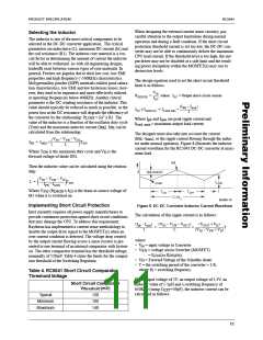
We recommend that the design include an input inductor
between the system +5V supply and the DC-DC converter
input described below. This inductor will serve to isolate the
+5V supply from noise occurring in the switching portion of
the DC-DC converter and to also limit the inrush current into
the input capacitors on power up. We recommend a value of
around 2.5µH.
MBR2035CT IF = 20A;Tj = 125°C
Motorola IF = 15A; Tj = 25°C
MBR1545CT IF = 15A;Tj = 125°C
Motorola IF = 20A; Tj = 25°C
< 0.84V
< 0.72V
< 0.58V
< 0.48V
MBR2015CTL IF = 20A;Tj = 150°C
Output Filter Capacitors
2.5µH
5V
Vin
Optimal ripple performance and transient response are
functions of the filter capacitors used. Since the 5V supply of
a PC motherboard may be located several inches away from
the DC-DC converter, input capacitance can play an impor-
tant role in the load transient response of the RC5041.
The higher the input capacitance, the more charge storage is
available for improving the current transfer through the FET.
Low “ESR” capacitors are best suited for this type of appli-
cation and can influence the converter's efficiency if not
chosen carefully. The input capacitor should be placed as
close to the drain of the FET as possible to reduce the effect
of ringing caused by long trace lengths.
1000µF, 10V
Electrolytic
0.1µF
65-5041-11
Figure 9. Input Filter
13

 RAYTHEON [ RAYTHEON COMPANY ]