VRS51C1000
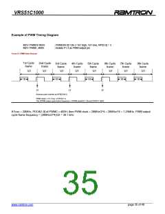
Example of PWM Timing Diagram
MOV PWMD0 #83H
MOV PWME, #08H
; PWMD04:0]=10h (=16T high, 16T low), NP02:0] = 3
; Enable P1.3 as PWM output pin
FIGURE 21: PWM TIMING DIAGRAM
1st Cycle
frame
2nd Cycle
frame
3rd Cycle
frame
4th Cycle
frame
5th Cycle
frame
6th Cycle
frame
7th Cycle
frame
8th Cycle
frame
32T
32T
32T
32T
32T
32T
32T
32T
16
16
16
16
16
1T
1T
1T
(Narrow pulse inserted by NP0[2:0]=3)
PWM clock= 1/T= Fosc / 2^(PDIV+1)
The SPWM output cycle frame frequency = SPWM clock/32 = [Fosc/2^(PDIV+1)]/32
If Fosc = 20MHz, PDCK[1:0] of PWMC = #03H, then PWM clock = 20MHz/2^4 = 20MHz/16 = 1.25MHz. PWM output
cycle frame frequency = (20MHz/2^4)/32 = 39.1 kHz.
______________________________________________________________________________________________
www.ramtron.com
page 35 of 48

 RAMTRON [ RAMTRON INTERNATIONAL CORPORATION ]