The device reports back with two bytes:
the first is the R2R offset DAC amount
(0..255), the second is the coarse
setting as a bit pattern: coarse bit 0
corresponds to Cz1, coarse bit 1 to
Cz2, resulting in valid data values of 0,
1, 3.
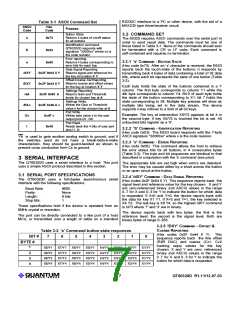
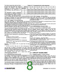
Table 3-3 'e' Command error code responses
BIT #
BYTE #
7
6
5
4
3
2
1
0
1
X8/Y1
X8/Y2
X8/Y3
X8/Y4
X7/Y1
X7/Y2
X7/Y3
X7/Y4
X6/Y1
X6/Y2
X6/Y3
X6/Y4
X5/Y1
X5/Y2
X5/Y3
X5/Y4
X4/Y1
X4/Y2
X4/Y3
X4/Y4
X3/Y1
X3/Y2
X3/Y3
X3/Y4
X2/Y1
X2/Y2
X2/Y3
X2/Y4
X1/Y1
X1/Y2
X1/Y3
X1/Y4
2
3
4
This information is useful in observing
circuit behavior for diagnostic purposes
during development. Values of Coarse
= 3 and Offset > 128 indicate excessive
X-to-Y coupling that can arise due to normal production
variances or component drift. The maximum limit the circuit
can tolerate is Coarse = 3, Offset = 255 before the signal
saturates and a key becomes inoperable.
3.2.8 '/EAv' COMMAND - SETTINGS
W
RITE
(Hex codes 0x2F 0x45 A v) Allows the gain and threshold
settings for a button to be written. 'A' is a single binary byte
specifying the address and 'v' is a single binary byte value of
the data to be written.
3.2.6 '/eA' COMMAND - SETTINGS
R
EPORTING
The addresses are calculated in an identical manner to those
for the /eA command above.
(Hex codes 0x2F 0x65 A) Allows the gain and threshold
settings for a specific button to be read back to the host. 'A' is
a single binary byte specifying the address of the data to be
read. Separate commands must be issued to read the gain
and threshold for each button as these values are held at
separate addresses, with the data for the threshold being
held in the address immediately following that for the gain.
Note that a change in the gain value of even one key will
cause the E6S3 to recalibrate all keys.
3.2.9 EEPROM WRITE
A
CCESS VIA /EA
See 3.2.7 for information on reading eeprom data.
V
The gain and threshold settings for all buttons are held in an
internal byte array, starting at address 100 (decimal). The
first two sequential bytes in this array hold the settings data
for button X1/Y1, the next two bytes hold the data for button
X2/Y1 and so on. The gain is held in the first byte (at the
lower address) and the threshold in the second byte.
The /EAv command can be used to write a byte to any of the
86 available internal eeprom locations. Like the /eA
command, byte 'A' is the address of the byte from 0xaa to
0xff. The byte 'v' should contain the 8-bit binary data to be
written to the address 'A'.
The first byte of eeprom is located at address 170 (decimal)
and can be written via the command string /EA where 'A' is
the binary byte 170 (0xaa). The highest location is at 255
(0xff).
The button memory addresses are calculated as follows for a
given key:
Multiply (X-1) times 2 to get M
So, if the key is on X6, M = (6-1)*2 = 10 (decimal).
3.2.10 'Ov' COMMAND - USER
P
ORT
W
RITE
(Hex codes 0x4F v) Writes the value ‘v’, an 8-bit binary byte,
to the QT60320’s 8 output port pins O1…O8.
Multiply (Y-1) times 16 to get N
So, if the key is on Y3, N = (3-1)*16 = 32 (decimal).
This feature can be used to drive LED’s via external buffers,
a self-oscillating acoustic sounder, or other peripheral device.
It can even be used in conjunction with the ‘I’ command
(below) to scan a set of external electromechanical keys (up
to 32 switches, e.g. in an 8x4 matrix) near the panel.
Add M + N + 100 to get the first of the two memory
addresses for the key.
Example: A key located at X4, Y3 would have its base
address at:
(4-1)*2 + (3-1)*16 + 100 = 32 + 6 + 100 = 138 (decimal)
3.2.11 'I' COMMAND - USER
P
ORT
R
EAD
(Hex code 0x49) Causes the QT60320D to return a binary
byte from the port pins I1…I4. The value is returned in the
lower nibble (bits 0,1,2,3) of the return byte. The high 4 bits
are held at zero.
The first byte, at address 138 decimal is the gain, while
address 139 has the threshold for X4/Y3. The address must
be sent as a binary number (packed into 8 bits, i.e. 0x8a and
0x8b in this example), NOT as the ASCII string ‘1 3 8’.
The QT60320D reports back with a single binary byte
containing the data requested.
4 - CIRCUIT GUIDELINES
3.2.7 EEPROM READ
ACCESS VIA /eA
4.1 POWER SUPPLY, PCB LAYOUT
It is possible to use part of the QT60320's internal eeprom as
'user storage'. This feature allows the elimination of a
separate eeprom associated with a host MCU, reducing
system cost. The QT60320D has 86 bytes of spare eeprom
available to the user for any function whatsoever. The
eeprom can be read and written using the same /eA and
/EAv commands used to examine and write key settings.
The power supply should be 5.0 volts +/- 10%. This can be
provided by a common 78L05 3-terminal regulator. LDO type
regulators are usually fine but can suffer from poor transient
load response; this will cause erratic key behavior.
If the power supply is shared with another electronic system,
care should be taken to assure that the supply is free of
digital spikes, sags, and surges which can adversely affect
the circuit. The QT60320D will track slow changes in Vcc, but
it can be adversely affected by rapid voltage steps and
impulse noise on the supply rail.
The first byte of eeprom is located at address 170 (decimal)
and can be read via the command string /eA where 'A' is the
binary byte 170 (0xaa). The highest location is at 255 (0xff).
LQ
8
QT60320D R1.11/12.07.03

 QUANTUM [ QUANTUM RESEARCH GROUP ]