must be placed immediately over a ground plane within a
A ceramic 0.1µF bypass capacitor should be placed very
millimeter), the resistance might need to be lowered. Observe close to the power pins of the IC.
the sensing pulses for flatness on their tops in the middle of a
Regulator stability: Most low power LDO regulators have
segment using a small coin and scope probe to make sure
the pulses fully settle before the falling edge (see app note
AN-KD02 Figure 7).
very poor transient stability, especially when the load
transitions from zero current to full operating current in a few
microseconds. With the QT411 this happens when the device
comes out of sleep mode. The regulator output can suffer
from hundreds of microseconds of instability at this time,
which will have a negative effect on acquisition accuracy.
The electrode can be made of a series chain of discrete
resistors with copper pads on a PCB, or from ITO (Indium Tin
Oxide, a clear conductor used in LCD panels and touch
screens) over a display. Thick-film carbon paste can also be
used, however linearity might be a problem as these films are
notoriously difficult to control without laser trimming or
scribing.
The linearity of the sensing strip is governed largely by the
linearity and consistency of the resistive element. Position
accuracy to within 5% is routinely achievable with good grade
resistors and a uniform construction method.
To assist with this problem, the QT411 waits 500µs after the
400µs taken to come out of sleep mode before acquiring to
allow power to fully stabilize. This delay is not present before
an acquisition burst if there is no preceding sleep state.
Use an oscilloscope to verify that Vdd has stabilized to within
5mV or better of final settled voltage before a burst begins.
The QT411 has specially enhanced power supply rejection
built in. This means that it is often possible to share the
regulator with other circuits. However, it is always advised to
be sure that Vdd is free from spikes and transients, and is
filtered sufficiently to prevent detection problems.
2.2 Cs Sample Capacitors
Cs1, Cs2 and Cs3 are the charge sensing sample capacitors;
normally they are identical in nominal value. They should be
of type X7R dielectric.
During development it is wise to first design a regulator onto
the PCB just for (and next to) the QT411, but allow for it to be
‘jumpered out’. If in development it is clear that there are no
problems with false detection or ‘angle noise’ even without a
separate regulator for the QT411, then the regulator can be
safely omitted.
The optimal Cs values depend on the thickness of the panel
and its dielectric constant. Lower coupling to a finger caused
by a low dielectric constant and/or thicker panel will cause the
position result to become granular and more subject to
position errors. The ideal panel is made of thin glass. The
worst panel is thick plastic. Granularity due to poor coupling
can be compensated for by the use of larger values of sample 2.5 PCB Layout and Mounting
capacitors.
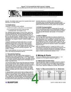
One form of PCB layout is shown in Figure 1-3. This is a
1-sided board; the blank side is simply adhered to the inside
of a 2mm thick (or less) control panel. Thicker panels can be
tolerated with additional position error due to capacitive ‘hand
shadow’ effects and will also have poorer EMC performance.
A table of suggested values for no missing position values is
shown in Table 1-2. Values of Cs smaller than those shown in
the table can cause skipping of position codes. Code skipping
may be acceptable in many applications where fine position
data is not required. Smaller Cs capacitors have the
advantage of requiring shorter acquisition bursts and hence
lower power drain.
The Figure 1-3 layout uses a series copper pads connected
with intervening series resistors in a row. The total resistance
between any two connection points can be in the range of
100K to 500K, with ~400K being a suitable target value.
Resistance values at the higher end of this range will
generate more sensitivity provided there is no ground plane
close underneath the electrode strip.
A human finger interpolates between the copper pads (if the
pads are narrow enough) to make a smooth output with no
apparent steps. The lateral dimension along the centre of
each electrode should be no wider than the expected
smallest diameter of finger touch, to prevent stepping of the
position response (if it matters).
Larger values of Cs improve granularity at the expense of
longer burst lengths and hence more average power.
Cs1, Cs2 and Cs3 should be X7R type, matched to within
10% of each other (ie, 5% tolerance) for best accuracy. The
PCB reference layout (Figure 1-3) is highly recommended. If
the Cs capacitors are poorly matched, position accuracy will
be affected and there could also be missing codes.
2.3 Rs Resistors
See Figure 1-1. Rs1, Rs2, and Rs3 are low value (typically
4.7K) resistors used to suppress the effects of ESD and
assist with EMC compliance. They are optional in most
cases.
It is also possible create an interleaved electrode array with
only 3 resistors between each channel’s connection point on
the strip. Interleaving eliminates stepping while reducing the
number of required resistors. Consult Quantum for further
details.
Resistive inks (such as ITO, Agfa OrgaconTM etc.) can also be
used if the resistance between connection points is in the
recommended range.
In addition, there are two 8.2K resistors required to split
channel SNS3B into the two constituent ends. These two
resistors should be placed close to the ends of the slider
strip.
The electrode strip can be made in various lengths up to at
least 80mm. The electrode width should be about 12mm wide
or more, as a rule. The strip can also be an arc or other
irregular shape. For a 360 degree wheel, use the QT511 or
consult Quantum for other options.
2.4 Power Supply
The usual power supply considerations with QT parts applies
also to the QT411. The power should be very clean and come
from a separate regulator if possible. This is particularly
critical with the QT411 which reports continuous position as
opposed to just an on/off output.
lQ
5
QT411-ISSG R6.01/1005

 QUANTUM [ QUANTUM RESEARCH GROUP ]