Figure 1-3 Conventional PCB Layout (1-sided)
Copper side faces away from the panel; the bare side is glued to the inside of the product.
element. The position data ceases to be reported when touch electrode afterwards, so that the drift compensation
detection is no longer sensed.
mechanism does not artificially create a threshold offset
during the iteration process. Between threshold changes, the
probe must be removed to at least 100mm from the panel.
1.6 Calibration
Calibration is possible via two methods:
1.8 Drift Compensation
1) Power up or power cycling (there is no reset input).
The device features an ability to compensate for slow drift
due to environmental factors such as temperature changes or
humidity. Drift compensation is performed under host control
via a special drift command. See Section 3.3.3 for further
details.
2) On command from the host via the SPI port
(Command 0x01: see Section 3.3.2).
The calibration period requires 10 burst cycles, which are
executed automatically without the need for additional SPI
commands from the host. The spacing between each Cal
burst is 1ms, and the bursts average about 31ms each, i.e.
the Cal command requires ~325ms to execute. The power up
calibration has 6 extra bursts to allow for power supply
stabilization, and requires a total of ~550ms to begin normal
operation.
1.9 Error Status
An error flag status is provided via a special command. An
error can only occur when a finger was touching the sensing
strip during power-on or recalibration, and then removed. In
this sequence of events, the finger is ‘calibrated away’ and is
not recognized as a touch. When the finger is removed, the
signals from the device are inverted and a position is reported
as though the strip has been touched. However, this position
report is in error.
Calibration should be performed when there is no hand
proximity to the element, or the results may be in error.
Should this happen, the error flag (bit 1 of the standard
response, see Section 3.3) will activate when the hand is
withdrawn. In most cases this condition will self-correct if drift
compensation is used, and it can thus be ignored. See
Section 1.9 below.
After any calibration event (i.e. a power-on cycle or a CAL
command) the next detection event should be checked to see
if it is in error by using the special error command. If it an
error is reported, the device should be immediately calibrated
again to restore normal function (Section 3.3.2).
Note: During calibration, the device cannot communicate.
DRDY will remain low during this interval.
1.7 Sensitivity Setting
The sensitivity of the slider area to finger detection is
dependent on the values of the three Cs capacitors (Section
2.2) and the threshold setting (Section 3.3.5). Larger values
of Cs increase sensitivity and also reduce granularity (missing
codes), at the expense of higher power consumption due to
longer acquisition bursts.
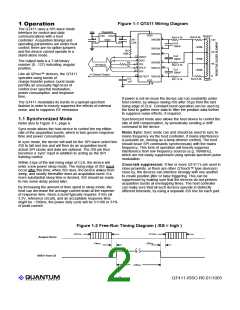
2 Wiring & Parts
The device should be wired according to Figure 1-1. An
examples of a PCB layout is shown in Figure 1-3.
2.1 Electrode Construction
The strip electrode should be a resistive element of between
200K to 500K ohms (400K nominal target value) between
each set of connection points, of a suitable length and width.
Under heavy capacitive loading (for example if the element
The threshold setting can be used to fine tune the sensitivity
of the sensing element. When setting the threshold, use the
smallest finger size for which detection is desired (normally a
6mm diameter spot), and probe at one of the two center
connection points where sensitivity is weakest. The linear
stretches between connection points are generally slightly
higher in sensitivity due to the collection of charge from two
channels.
Table 1-2 Recommended Cs vs. Materials
Thickness,
Acrylic
Borosilicate glass
A ‘standard finger’ probe can be made by taking a piece of
metal foil of the required diameter, gluing it on the end of a
cylinder of sponge rubber, and connecting it to ground with a
wire. This probe is pressed against the panel centered on one
of the middle two connection points; the threshold parameter
is iterated until the sensor just detects. It is important to push
the probe into the panel quickly and not let it linger near the
mm
(
εR =2.8)
10nF
22nF
47nF
100nF
-
(
εR =4.8)
5.6nF
10nF
0.4
0.8
1.5
2.5
3.0
4.0
22nF
39nF
47nF
-
100nF
lQ
4
QT411-ISSG R6.01/1005

 QUANTUM [ QUANTUM RESEARCH GROUP ]