In addition, the OUT pin can be made either active low or
active high (Section 2.7.1).
2.8.5 OBJ (OBJECT) DETECTION
M
ODE
This mode is useful to do a ‘learn by example’ calibration.
Typically, a test object is placed at the electrode in such a
way as to create a 50ꢀ signal level change relative to a
normal, full presentation of the object. The QT310 is then
calibrated in OBJ mode. Calibration in OBJ mode should
never be done with a full presentation of signal, as this will
create a marginal, unreliable detection.
2.8.4.1 BG1 Mode (volatile reference)
In BG1 mode, the reference is set via recalibration initiated
using the /CAL_CLR pin or on power-up. The resulting
reference level is not stored into EEPROM. Max On-Duration
and drift compensation are able to function normally.
BG1 mode is useful when the signal can change slightly over
time and temperature, and it is useful to track these changes
without a loss of sensitivity.
This mode is suited to material detection, fluid level sensing,
and similar applications.
In OBJ mode, on calibration the current signal value is
recorded as a fixed threshold point and stored to EEPROM.
2.8.4.2 BG2 Mode (stored reference)
In BG2 mode, the reference level is fixed and stored in
internal EEPROM. Drift compensation (Section 2.2) can be
used, but changes to the reference due to drift compensation
are not updated to EEPROM. Max On-Duration can also be
enabled (Section 2.6); if a MOD timeout occurs, the new
reference will be stored in EEPROM.
The hysteresis level is made relative to the fixed threshold,
and can be altered as with the BG modes. If hysteresis is too
large, the sensor can ‘stick’ on; hysteresis should normally be
set to a small value, just enough to prevent output chatter.
Hysteresis can also be made intentionally large, for example
for ‘bang-bang’ fluid level sensing, where an ‘upper’ level is
calibrated using OBJ, and a ‘lower’ cut-out level is defined by
the hysteresis value. The sensor must have SD = positive for
this mode (Section 2.8.2).
The reference is normally set during recalibration when the
/CAL_CLR pin pulses low (Section 1.6); the resulting
reference value is then stored in EEPROM. At power-up the
part automatically restores this reference level and runs
without another recalibration.
OBJ mode does not make use of a reference level and does
not allow drift compensation or Max On-Duration to operate.
The threshold point is fixed for all time until another
The reference value can also be entered numerically via the
cloning process (Table 4-1, page 14) to precisely replicate the /CAL_CLR signal is received.
calibration point across many devices.
The OBJ threshold value can also be entered numerically via
BG2 mode is useful when it is desired to lock in the reference the cloning process (Table 4-1, page 14) to precisely replicate
to prevent changes on startup, for example to replace
mechanical switches in process controls.
the threshold point across many devices.
Positive, negative detection mode behavior: In OBJ mode
OUT can be made active on either positive or negative signal
changes (Section 2.8.2). The signal direction selection affects
which side of the threshold the hysteresis level is placed after
calibration.
The OUT pin can be made either active low or active high
(Section 2.7.1).
U1
Vdd
1
6
2
7
3
5
OUT1
/CAL
OUT
Vdd
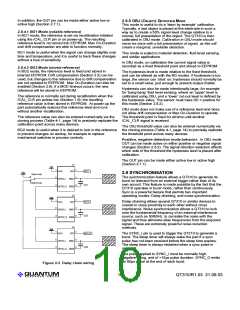
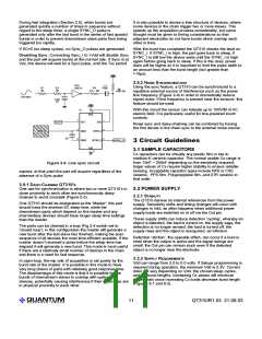
2.9 SYNCHRONISATION
Open Loop
The synchronization feature allows a QT310 to generate its
burst on demand from an external trigger rather than of its
own accord. This feature is made possible by the fact that the
QT310 operates in burst mode, rather than continuously.
Sync is a powerful feature that permits two important
operating modes: Daisy-chaining, and noise synchronization.
SENSOR 1
/SYNC_I SNS1
/SYNC_O SNS2
Closed Loop
CS1
U2
Vdd
1
6
2
7
3
5
OUT2
Daisy-chaining allows several QT310 or similar devices to
coexist in close proximity to each other without cross
interference. Noise synchronization allows a QT310 to lock
onto the fundamental frequency of an external interference
source, such as 50/60Hz, to correlate the noise with the
signal and thus eliminate alias frequencies from the acquired
signal. These are extremely powerful noise reduction
methods.
/CAL
OUT
SENSOR 2
/SYNC_I SNS1
/SYNC_O SNS2
CS2
Un
Vdd
1
6
2
7
3
5
OUT_N
/CAL
OUT
The SYNC_I pin is used to trigger the QT310 to generate a
burst. The sleep timer will always wake the part if a sync
pulse has not been received before the sleep time expires.
The sleep timer is always restarted when a sync pulse is
received.
SENSOR N
/SYNC_I SNS1
/SYNC_O SNS2
CS3
The pulse applied to SYNC_I must be normally high,
negative-going, and of >15µs pulse duration. SYNC_O emits
an 80µs pulse at the end of each burst.
Figure 2-3 Daisy chain wiring
LQ
10
QT310/R1.03 21.09.03

 QUANTUM [ QUANTUM RESEARCH GROUP ]