Hysteresis should be set to between 10ꢀ and 40ꢀ of the
threshold value for best results.
2.2.1 NEGATIVE
Range: 0..255; Default: 2; 255 disables
Compensation for drift with decreasing Cx
D
RIFT
COMPENSATION (NDC)
If HYS is set to 0, there will be no hysteresis (0ꢀ).
NDC corrects the reference when the internal signal is drifting
up, i.e. Cx is decreasing (see Section 2.8.1). Every interval of
time the device checks for the need to move its reference
level in the positive internal direction (negative Cx direction) in
accordance with signal drift. The resulting timing interval for
this adjustment is Tndc.
If THR = 10 and HYS = 2, the hysteresis zone will represent
20ꢀ of the threshold level. In this example the ‘hysteresis
zone’ is the region from 8 to 10 counts of signal level. Only
when the signal falls back to 7 will the OUT pin become
inactive.
This should normally be faster than positive drift
compensation in order to compensate quickly for the removal
of a touch or obstruction from the electrode after a MOD
recalibration (Section 1.5.3).
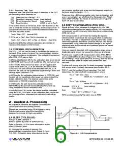
2.5 DETECT INTEGRATORS (DIA, DIB, DIS)
DIAT
DIBT
DIS
Range: 1..256 Default: 10
Range: 1..256 Default: 10
Range: 0, 1
Default: 1
Affects response time Tdet.
Use NDC+1 to compute actual drift timings.
See Figure 2-2 for operation.
2.2.2 POSITIVE
Range: 0...255 Default: 100; 255 disables
Compensation for drift with increasing Cx
D
RIFT
COMPENSATION (PDC)
It is usually desirable to suppress detections generated by
sporadic electrical noise or from quick contact with an object.
To accomplish this, the QT310 incorporates a pair of
detection integrator (‘DI’) counters that serve to filter out
This corrects the reference when the signal drifting down, i.e.
Cx is increasing (see Section 2.8.1). Every interval of time the sporadic noise. These counters can also have the effect of
device checks for the need to move its reference level in the
negative internal direction (positive Cx direction) in
accordance with signal drift. The resulting timing interval for
this adjustment is Tpdc.
slowing down response time if desired.
DI counters act as a powerful noise filter.
These DI counters work with spread-spectrum modulation to
drastically suppress the effects of external RFI. See page 13
for details.
This value should not be set too fast, since an approaching
finger could be compensated for partially or entirely before
even touching the sense electrode.
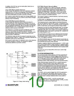
DIA / DIAT: The first counter, DIA, increments after each
burst if the signal threshold has been exceeded, until DIA
reaches its terminal count DIAT, after which the OUT pin is
activated. If the signal falls below the threshold level prior to
reaching DIAT, DIA is immediately reset to zero.
Use PDC+1 to compute actual drift timings.
2.3 THRESHOLD (THR)
Range: 1..255; Default: 6
Affects sensitivity; not used in OBJ mode.
DIA can also be viewed as a 'consensus' filter that requires
signal threshold crossings over ‘T’ successive bursts to create
an output, where ‘T’ is the terminal count (DIAT).
The detection threshold is measured in terms of counts of
signal deviation with respect to the reference level. Higher
threshold counts equate to less sensitivity since the signal
must travel further in order to cross the detection point.
DIB / DIBT: If OUT has been active and the signal falls below
the hysteresis level, a second detection integrator, DIB,
counts up.
If the signal equals or exceeds the threshold value, a
detection can occur. The detection will end only when the
signal become less than the hysteresis
level.
When DIBT is reached, OUT is deactivated.
THR is not used in OBJ mode (Section
2.8.5). In OBJ mode the threshold is set by
example during calibration.
2.4 HYSTERESIS (HYS)
Range: 0...255; Default: 2; 0 disables
Affects detection stability.
Hysteresis is measured in terms of counts
of signal deviation relative to the threshold
level. Higher values equate to more
hysteresis. The device will become inactive
after a detection when the Cx level moves
below THR-HYS in normal mode or above
THR+HYS in absence mode (Section2.8.2)
Hysteresis helps prevents chattering of the
OUT pin.
If HYS is set to a value equal or greater than
THR, the device may malfunction.
Figure 2-2 Detect Integrators Operation (Section 2.5)
LQ
7
QT310/R1.03 21.09.03

 QUANTUM [ QUANTUM RESEARCH GROUP ]