are crowded together with a rep rate that depends entirely on
the burst lengths (Section 1.5.1).
1.5.4 RESPONSE
Response time Tdet from the onset of detection to the OUT
pin becoming active depends on:
TIME, TDET
Response time, drift compensation rate, max on-duration, and
power consumption are all affected by this parameter. A high
value of SC will allow the device to consume very low power
but it will also be very slow.
Tbs Burst spacing (Section 1.5.2)
DIT Detection Integrator Target (user setting)
DIS Detect Integration Speed
Tbd Burst duration
(user setting)
(if DIS is set to ‘fast’)
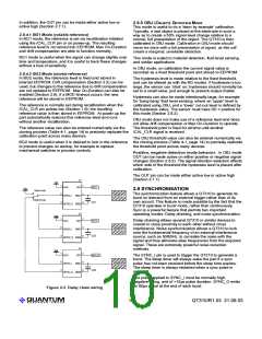
2.2 DRIFT COMPENSATION (PDC, NDC)
Signal drift can occur because of changes in Cx, Cs, Vdd,
electrode contamination and ageing effects. It is important to
compensate for drift, otherwise false detections and sensitivity
shifts can occur.
If the control bit DIS is normal (0), then Tdet depends on the
rate at which the bursts are acquiring, and the value of DIT. A
DIT number of bursts must confirm the detection before the
OUT line becomes active:
Tdet = Tbs x DIT (normal DIS)
Drift compensation is performed by making the signal’s
reference level slowly track the raw signal while no detection
is in effect. The rate of adjustment must be performed slowly,
otherwise legitimate detections could be affected. The device
compensates using a slew-rate limited change to the signal
reference level; the threshold and hysteresis points are slaved
to this reference.
If DIS is set to ‘fast’, then Tdet is computed as:
Tdet = (SC x Tsc) + (DIT x (Tbd + 2.25ms)) (fast DIS)
Quantum’s QT3View software calculates an estimate of
response time based on this formula.
1.6 EXTERNAL RECALIBRATION
Once an object is detected, drift compensation stops since a
legitimate signal should not cause the reference to change.
The /CAL_CLR pin can be used to recalibrate the sensor on
demand. A low pulse of at least Tbs (burst spacing) duration
is require to initiate a recalibration. The calibration occurs just
after /CAL_CLR returns high.
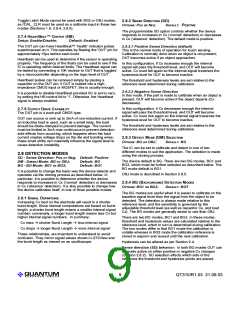
Positive and negative drift compensation rates (PDC, NDC)
can be set to different values (Figure 2-1). This is invaluable
for permitting a more rapid reference recovery after the device
has recalibrated while an object was present and then
removed.
In BG1 mode (Section 2.8.4), the calibration data is not stored
in EEPROM, and the part will recalibrate after each power up.
In BG1 mode, if the device has been set for Toggle Latch
output mode, the /CAL_CLR pin becomes an output reset
control and the part cannot be recalibrated via /CAL_CLR.
However the part can be recalibrated by powering it down and
back up again (Section 2.7.3).
Positive drift occurs when the Cx slowly increases. Negative
drift occurs when Cx slowly decreases (see Section 2.8.1).
PDC+1 sets the number of burst spacings, Tbs, that
determines the interval of drift compensation, where:
Tbs = Tbd + (SC x Tsc)
where SC > 0 (Section 1.5.2)
-or-
In BG2 mode, the calibration data is stored in EEPROM, and
the part will not recalibrate after power up, using instead the
stored calibration data. The internal eeprom has a life
expectancy of 100,000 erase/write cycles.
Tbs = Tbd + 2.25ms
where SC = 0 (Section 1.5.2)
In OBJ mode, the part stores the calibration data into
EEPROM and the part will not recalibrate after power up,
using instead the stored calibration data.
Example: PDC = 9,
Tbs = 100ms
then
(user setting)
In both BG2 and OBJ mode, the device must be calibrated
using the /CAL_CLR input, or the calibration data can be set
via cloning process, otherwise the calibration data will be
invalid.
Tpdc = (9+1) x 100ms = 1 sec
NDC operates in exactly the same way as PDC.
2 - Control & Processing
All acquisition functions are digitally controlled and
can be altered via the cloning process.
Signals are processed using 16 bit integers, using
Quantum-pioneered algorithms specifically
designed to provide for high survivability.
2.1 SLEEP CYCLES (SC)
Range: 0..255; Default: 1
Affects speed & power of entire device.
Refer to Section 1.5.2 for more information on the
effect of Sleep Cycles.
SC changes the number of intervals Tsc
separating two consecutive burst (Figure 1-7 and
1-8). SC = 0 disables sleep intervals and bursts
Figure 2-1 Drift Compensation
LQ
6
QT310/R1.03 21.09.03

 QUANTUM [ QUANTUM RESEARCH GROUP ]