QN8007B/8007LB
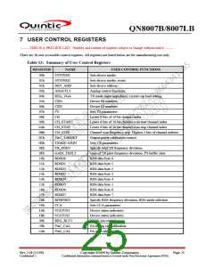
7 USER CONTROL REGISTERS
-------- THIS IS A PREVIEW LIST. Number and content of registers subject to change without notice --------
There are 28 user accessible control registers. All registers not listed below are for manufacturing use only.
Table 13: Summary of User Control Registers
REGISTER
NAME
SYSTEM1
USER CONTROL FUNCTIONS
Sets device modes.
00h
01h
02h
03h
04h
05h
06h
07h
08h
09h
0Ah
0Bh
0Ch
0Dh
0Eh
0Fh
10h
11h
12h
13h
14h
15h
16h
17h
18h
19h
1Ah
1Bh
49h
59h
5Ah
SYSTEM2
DEV_ADD
ANACTL1
REG_VGA
CID1
Sets device modes, resets.
Sets device address.
Analog control functions.
TX mode input impedance, crystal cap load setting.
Device ID numbers.
CID2
I2S
Device ID numbers.
Sets I2S parameters.
CH
Lower 8 bits of 10-bit channel index.
Lower 8 bits of 10-bit channel scan start channel index.
Lower 8 bits of 10-bit channel scan stop channel index.
Channel scan frequency step. Highest 2 bits of channel indexes.
Output power calibration control.
Sets TX parameters.
CH_START
CH_STOP
CH_STEP
PAC_TARGET
TXAGC GAIN
TX_FDEV
GAIN_TXPLT
RDSD0
Specify total TX frequency deviation.
Gain of TX pilot frequency deviation, I2S buffer clear.
RDS data byte 0.
RDSD1
RDS data byte 1.
RDSD2
RDS data byte 2.
RDSD3
RDS data byte 3.
RDSD4
RDS data byte 4.
RDSD5
RDS data byte 5.
RDSD6
RDS data byte 6.
RDSD7
RDS data byte 7.
RDSFDEV
CCA
Specify RDS frequency deviation, RDS mode selection.
Sets CCA parameters.
STATUS1
STATUS2
REG_XLT3
PAC_CAL
PAG_CAL
Device status indicators.
Device status indicators.
XCLK pin control.
PA tuning cap calibration.
PA gain calibration.
Rev 2.09 (11/09)
Confidential A
Copyright ©2009 by Quintic Corporation
Confidential Information contained herein is covered under Non-Disclosure Agreement (NDA).
Page 25

 QUANTUM [ QUANTUM RESEARCH GROUP ]