QN8007B/8007LB
5.2 3-Wire Serial Control Interface
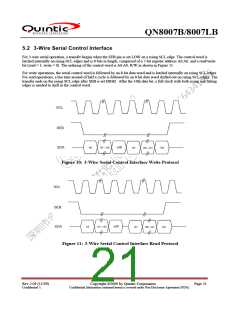
For 3-wire serial operation, a transfer begins when the SEB pin is set LOW on a rising SCL edge. The control word is
latched internally on rising SCL edges and is 8 bits in length, comprised of a 7-bit register address A6:A0, and a read/write
bit (read = 1, write = 0). The ordering of the control word is A6:A0, R/W as shown in Figure 11.
For write operations, the serial control word is followed by an 8-bit data word and is latched internally on rising SCL edges.
For read operations, a bus turn-around of half a cycle is followed by an 8-bit data word shifted out on rising SCL edges. The
transfer ends on the rising SCL edge after SEB is set HIGH. After the 16th data bit, a full clock with both rising and falling
edges is needed to shift in the control word.
Figure 10: 3-Wire Serial Control Interface Write Protocol
Figure 11: 3-Wire Serial Control Interface Read Protocol
Rev 2.09 (11/09)
Confidential A
Copyright ©2009 by Quintic Corporation
Confidential Information contained herein is covered under Non-Disclosure Agreement (NDA).
Page 21

 QUANTUM [ QUANTUM RESEARCH GROUP ]