QN8007B/8007LB
5 CONTROL INTERFACE PROTOCOL
The QN8007 supports 2- wire and 3-wire serial interfaces. The interface selection is controlled by the MOD pin which
determines whether a 2- wire or a 3-wire serial interface will be used. MOD = HIGH selects a 3-wire bus and LOW selects
a 2-wire bus.
5.1 2-Wire Serial Control Interface
The 2-wire bus is a simple bi-directional bus interface. The bus requires only serial data (SDA) and serial clock (SCL)
signals. The bus is 8-bit oriented. Each device is recognized with a unique address. Each register is also recognized with a
unique address. A third line (SEB) is used to choose the device address configuration. SEB = LOW selects the default
address (0101011), SEB = HIGH selects register defined addressing. The L2 bus operates with a maximum frequency of
400 kHz. Each data put on the SDA must be 8 bits long (Byte) from MSB to LSB and each byte sent should be
acknowledged by an “ACK” bit. In case a byte is not acknowledged, the transmitter should generate a stop condition or
restart the transmission. If a stop condition is created before the whole transmission is completed, the remaining bytes will
keep their old setting. In case a byte is not completely transferred, it will be discarded.
Data transfer to and from the QN8007 can begin when a start condition is created. This is the case if a transition from HIGH
to LOW on the SDA line occurs while the SCL is HIGH. The first byte transferred represents the address of the IC plus the
data direction. The default IC address is 0101011. A LOW LSB of this byte indicates data transmission (WRITE) while a
HIGH LSB indicates data request (READ). This means that the first byte to be transmitted to the QN8007 should be “56”
for a WRITE operation or “57” for a READ operation.
The second byte is the starting register address (N) for write/read operation. The following bytes are register data for
address N, N+1, N+2, etc. There is no limit on the number of bytes in each transmission. A transmission can be terminated
by generating a stop condition, which is SDA transition from LOW to HIGH while SCL is HIGH. For write operation,
master stops transmission after the last byte. For read operation, master doesn’t send ACK after receiving the last read back
byte; then stops the transmission.
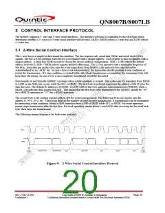
The following timing diagram is for both write and read.
DEVICE ADD
READ/WRITE
ACK
REG ADD
ACK
DATA
ACK
Figure 9: 2-Wire Serial Control Interface Protocol
Rev 2.09 (11/09)
Confidential A
Copyright ©2009 by Quintic Corporation
Confidential Information contained herein is covered under Non-Disclosure Agreement (NDA).
Page 20

 QUANTUM [ QUANTUM RESEARCH GROUP ]