PE43704
Product Specification
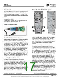
Figure 31. Evaluation Board Layout
Evaluation Kit
The Digital Attenuator Evaluation Board (EVB) was
designed to ease customer evaluation of the
PE43704 Digital Step Attenuator. PE43704 EVB
supports direct-parallel, latched-parallel, and serial
modes.
A0
Evaluation Kit Setup
Connect the EVB with the USB dongle board and
USB cable as shown in Figure 30.
Figure 30. Evaluation Kit
PRT-13505
DSA in Parallel Mode. Ensure that the software
GUI is set to Latched-Parallel mode. Use the
software GUI to enable the desired attenuation
state. The software GUI automatically programs
the DSA each time an attenuation state is
enabled.
Direct-Parallel Programming Procedure
Direct-parallel programming is suitable for manual
operation without software programming. For
manual direct-parallel programming, position the
Parallel/Serial (P/S) select switch to the Parallel (or
left) position. The LE pin of J1 (pin 15) must be tied
to HIGH voltage. Switches D0–D6 are SP3T
switches that enable the user to manually program
the parallel bits. When D0–D6 are toggled to the
‘HIGH’ position, logic high is presented to the
parallel input. When toggled to the ‘LOW’ position,
logic low is presented to the parallel input. Setting
D0–D6 to the ‘AUTO’ position presents as OPEN,
which is set for software programming of Latched-
Parallel and Serial mode. Table 8 depicts the
parallel programming truth table.
Serial-Addressable Programming Procedure
For automated serial programming, connect the
USB dongle board and cable that is provided with
the Evaluation Kit (EVK) from the USB port of the
PC to the J1 header of the PE43704 EVB, and set
the D0–D6 SP3T switches to the ‘AUTO’ toggle
position. Position the Parallel/Serial (P/S) select
switch to the Serial (or right) position. Prior to
programming, the user must define an address
setting using the HDR4 header pin. Jump the
middle row of pins on the HDR4 header (A0–A2)
to the lower row of pins to set logic low, or jump
the middle row of pins to the upper row of pins to
set logic high. If the HDR4 pins are left open, then
000 becomes the default address. The software
GUI is written to operate the DSA in Serial mode.
Use the software GUI to enable each setting to
the desired attenuation state. The software GUI
automatically programs the DSA each time an
attenuation state is enabled.
Latched-Parallel Programming Procedure
For automated latched-parallel programming,
connect the USB dongle board and cable that is
provided with the Evaluation Kit (EVK) from the
USB port of the PC to the J1 header of the
PE43704 EVB, and set the D0–D6 SP3T switches
to the ‘AUTO’ position. Position the Parallel/Serial
(P/S) select switch to the Parallel (or left) position.
The evaluation software is written to operate the
Document No. DOC-16514-6 |
www.psemi.com
©2012-2013 Peregrine Semiconductor Corp. All rights reserved.
Page 17 of 20
Logo updated under non-rev change. Peregrine products are protected under one or more of the following U.S. Patents: http://patents.psemi.com

 PSEMI [ Peregrine Semiconductor ]