1
Selection Chart
DPM Type
Number of dPwerTM POLs
and Auxiliary devices that
can be controlled
Active
Addresses
Number of
Groups
Number of
Interrupts
Number of
Parallel
Buses
Number of
Auxiliary
Devices
DM7304G
DM7308G
DM7316G
DM7332G
4
8
00…03
00…07
00…15
00…31
2
2
3
4
2
2
3
4
2
4
4
8
4
4
4
4
16
32
2
Ordering Information
DM
73
xx
G
–
yyyyy
–
zz
Packaging Option 1)
:
B1 – 50pcs Tube
B2 – 10pcs Tube
R100 – 100pcs T&R
Product
family:
dPwer Power
Management
Devices
Series: Number of
RoHS compliance:
dPwerTM POLs and G - RoHS compliant
5-digit identifier
assigned by
Power-One for
each unique
configuration file
Digital
Power
Manager
Auxiliary devices:
04 – 4 devices
08 – 8 devices
16 – 16 devices
32 – 32 devices
for all six substances
______________________________________
1
Packaging option is used only for ordering and not included in the part number printed on the DPM label.
The evaluation board is available in only one configuration: DM7300-KIT-HKS
2
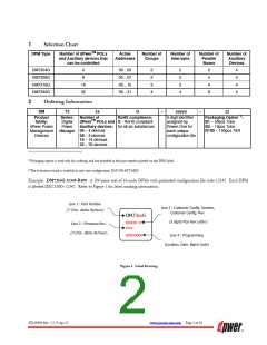
Example: DM7316G-12345-R100: A 100-piece reel of 16-node DPMs with preloaded configuration file code 12345. Each DPM
is labeled DM7316G-12345. Refer to Figure 1 for label marking information.
Line 1 : Part Number
Line 2 : Customer Config. Number,
(7 Char. Alpha Numeric)
Customer Config. Rev.
DM73xxG
(5 digits Plus Rev Letter)
xxxxx x
Line 3 : Firmware Rev.
xxxxxxx
(3 Char. Alpha Numeric)
Line 4 : Programming
(Location, Date, Batch Code)
Figure 1. Label Drawing
ZD-00896 Rev. 5.2, 9-Apr-13
www.power-one.com Page 2 of 36

 POWER-ONE [ POWER-ONE ]