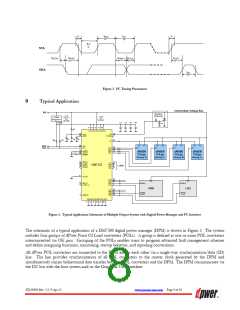
In this application, besides POL converters, the DPM also controls and monitors two auxiliary devices – a Voltage
Regulation Module (VRM) and a Low Dropout Regulator (LDO). While these devices are not dPwer compliant and
may not even be manufactured by Power-One, they are integrated into the system by communicating with the DPM
via their Enable pins connected to ENX outputs of the DPM. In addition, the DPM monitors status of the auxiliary
devices via its PGX inputs connected to Power Good and Error Flag outputs of the auxiliary devices. The DPM can
control and monitor four or more independent auxiliary devices.
The DPM can also trigger an optional crowbar circuit and provide undervoltage and overvoltage protections of the
intermediate bus voltage. In addition, the DPM can be controlled by a host system via the interrupt inputs, RES_N
and the ACFAIL_N inputs.
10
Description
The DM7300 series DPMs perform translation between the I2C interface connected to a host system or the Graphical
User Interface and the SD communication bus connected to dPOL converters. In addition, DPMs carry out
programming, monitoring, data storage, POL group management, hot-swap control, protection, and control and
monitoring of auxiliary devices.
The DPMs can be controlled via the GUI or directly via the I2C bus by using specific commands described in the
“DPM Programming Manual”.
10.1
DPM Memory
The DPM memory consists of RAM and non-volatile memory (Flash). The RAM is used for programming operations
and manipulation of the various blocks of configuration, setup, status, and monitoring registers. Non-volatile memory
is used to store programming and configuration data. Flash memory holds DPM set-up registers, POL set-up
registers, monitoring data, and user memory data. Setup registers for the DPM and the POL converters are protected
by CRCs that are checked during programming of POL converters and at the power-up of the DPM.
The LCK_N pin and the write protection register WP limit the write access to the memory blocks in the DPM and
POL converters. The WP register content is defaulted to write protect upon powering up the DPM.
10.1.1 Write Protection
There are hardware-based and software-based memory write protections. The hardware protection takes precedence
over the software protection.
10.1.1.1 Hardware Protection
The LCK_N pin enables the hardware memory write protection. If the pin is pulled low, the hardware lock is active
and the memory blocks are then read-only. I2C write commands to the DPM return an error code (0x00). The write
commands to the POL converters bypassing the DPM are also disabled. If the pin is left floating, the hardware lock is
disabled and the software write protection is active.
10.1.1.2 Software Protection
Software write protection allows users to protect the various memory blocks from being overwritten through the I2C
bus. At the power-up the WP register is defaulted to write protect.
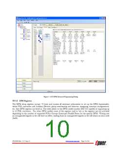
Software write protection can be disabled by checking appropriate boxes in the Write Protection subsection of the
DPM/Program/Advanced dialog shown in Figure 4 or via the I2C bus by writing directly into the register. Write
protections are automatically restored when the DPM’s input power is recycled.
ZD-00896 Rev. 5.2, 9-Apr-13
www.power-one.com Page 9 of 36

 POWER-ONE [ POWER-ONE ]