S/UNI®-8x155 ASSP Telecom Standard Product Data Sheet
Released
11 Normal Mode Register Descriptions
Normal mode registers are used to configure and monitor the operation of the S/UNI-8x155.
Normal mode registers are selected when TRS (A[13]) is low.
Test mode registers are used to enhance the testability of the S/UNI-1x155. Refer to section 12
for information about test registers.
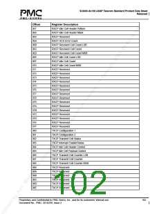
11.1 Register Memory Map
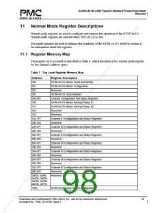
The register set is accessed as described in Table 8, which describes every normal mode register
for the channel’s address space.
Table 7 Top Level Register Memory Map
Address
000
001
Register Description
S/UNI-8x155 Master Reset and Identity
S/UNI-8x155 Master Configuration
Reserved
002
003
004-0FF
100
101
102
S/UNI-8x155 Clock Monitors
Channel Configuration and Status Registers
S/UNI-8x155 Master Interrupt Status #1
S/UNI-8x155 Master Interrupt Status #2
Reserved
103
Reserved
104-1FF
200-203
204-2FF
300-303
304-3FF
400-403
404-4FF
500-503
504-5FF
600-603
604-6FF
700-703
704-7FF
800-803
Channel #1 Configuration and Status Registers
Reserved
Channel #2 Configuration and Status Registers
Reserved
Channel #3 Configuration and Status Registers
Reserved
Channel #4 Configuration and Status Registers
Reserved
Channel #5 Configuration and Status Registers
Reserved
Channel #6 Configuration and Status Registers
Reserved
Channel #7 Configuration and Status Registers
Reserved
0x806, 0x906,
0xA06, 0xB06,
0xC06, 0xD06,
0xE06, 0xF06.
Reserved
1000
S/UNI-8x155 Clock Source Configuration
Proprietary and Confidential to PMC-Sierra, Inc., and for its customers’ internal use.
Document No.: PMC- 2010299, Issue 2
98

 PMC [ PMC-SIERRA, INC ]