S/UNI®-8x155 ASSP Telecom Standard Product Data Sheet
Released
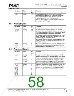
Pin Name
Type
Pin
No.
Function
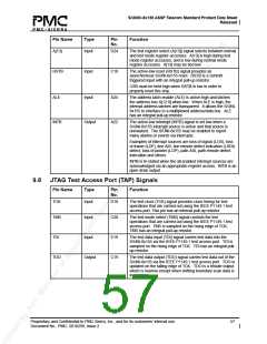
TRSTB
Input
C17
The active-low test reset (TRSTB) signal provides an
asynchronous S/UNI-8x155 test access port reset via the
IEEE P1149.1 test access port. TRSTB is a Schmitt
triggered input with an integral pull-up resistor.
Note that when not being used, TRSTB may be tied low or
connected to the RSTB input.
9.9 Analog Signals
Pin Name
Type
Pin
No.
Function
APREF0
APREF1
Analog
AH17
The APSO transmit reference (APREF0 and APREF1)
analog pins are provided to create calibrated currents for the
PECL output transceivers APS[1:0]+/-. See the High Speed
PECL Interfaces and APS sections for more details.
AH18
A 1.07 Kohm resistor is connected across the APREF0 and
APREF1 pins when the APSI[1:0]+/- and APSO[1:0]+/- are
terminated with one termination network.
A 2.15 Kohm resistor is connected across the APREF0 and
APREF1 pins when the APSO[1:0]+/- terminated using two
termination networks.
ATB[0]
ATB[1]
Analog
P5
R5
The receive and transmit analog test ports (ATB[1:0]). These
pins are used for manufacturing testing only and should be
tied to the analog ground plane (AVS).
9.10 Power and Ground
Pin Name
Type
Pin
No.
Function
QAVD
Analog
Power
U5
The quiet power (QAVD) pin for the analog core. QAVD
should be connected to well-decoupled analog +3.3V supply.
Please see the Operation section for detailed information.
QAVS
Analog
Ground
V3
The quiet ground (QAVS) pin for the analog core. QAVS
should be connected to analog ground of the QAVD supply.
Please see the Operation section for detailed information.
AVD[0]
AVD[1]
AVD[2]
AVD[3]
AVD[4]
AVD[5]
AVD[6]
AVD[7]
AVD[8]
Analog
Power
N2
P3
P1
R2
R1
U1
U4
V4
W1
The analog power (AVD[8:0]) pins for the analog core. The
AVD pins should be connected through passive filtering
networks to a well-decoupled +3.3V analog power supply.
Please see the Operation section for detailed information.
Proprietary and Confidential to PMC-Sierra, Inc., and for its customers’ internal use.
Document No.: PMC- 2010299, Issue 2
58

 PMC [ PMC-SIERRA, INC ]