S/UNI®-8x155 ASSP Telecom Standard Product Data Sheet
Released
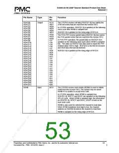
Pin Name
Type
Pin
No.
Function
A[13]
Input
D24
The test register select (A[13]) signal selects between normal
and test mode register accesses. A[13] is high during test
mode register accesses, and is low during normal mode
register accesses. A[13] may be tied low.
RSTB
Input
C18
The active-low reset (RSTB) signal provides an
asynchronous S/UNI-8x155 reset. RSTB is a Schmitt
triggered input with an integral pull-up resistor.
CSB must be held high when RSTB is low in order to
properly reset this chip.
ALE
Input
A24
A22
The address latch enable (ALE) is active-high and latches
the address bus A[12:0] when low. When ALE is high, the
internal address latches are transparent. It allows the S/UNI-
8x155 to interface to a multiplexed address/data bus. ALE
has an integral pull-up resistor.
The active-low interrupt (INTB) signal is set low when a
S/UNI-8x155 interrupt source is active and that source is
unmasked. The S/UNI-8x155 may be enabled to report
many alarms or events via interrupts.
INTB
Output
Examples of interrupt sources are loss of signal (LOS), loss
of frame (LOF), line AIS, line remote defect indication (LRDI)
detect, loss of pointer (LOP), path AIS, path remote defect
indication and others.
INTB is tri-stated when the all enabled interrupt sources are
acknowledged via an appropriate register access. INTB is an
open drain output.
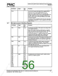
9.8 JTAG Test Access Port (TAP) Signals
Pin Name
Type
Pin
Function
No.
TCK
Input
D18
C20
The test clock (TCK) signal provides clock timing for test
operations that are carried out using the IEEE P1149.1 test
access port. This pin has an internal pull-up resistor.
The test mode select (TMS) signal controls the test
operations that are carried out using the IEEE P1149.1 test
access port. TMS is sampled on the rising edge of TCK.
TMS has an integral pull-up resistor.
The test data input (TDI) signal carries test data into the
S/UNI-8x155 via the IEEE P1149.1 test access port. TDI is
sampled on the rising edge of TCK. TDI has an integral pull-
up resistor.
The test data output (TDO) signal carries test data out of the
S/UNI-8x155 via the IEEE P1149.1 test access port. TDO is
updated on the falling edge of TCK. TDO is a tristate output
which is inactive except when shifting boundary scan data is
in progress.
TMS
TDI
Input
Input
E19
C19
TDO
Output
Proprietary and Confidential to PMC-Sierra, Inc., and for its customers’ internal use.
Document No.: PMC- 2010299, Issue 2
57

 PMC [ PMC-SIERRA, INC ]