S/UNI®-8x155 ASSP Telecom Standard Product Data Sheet
Released
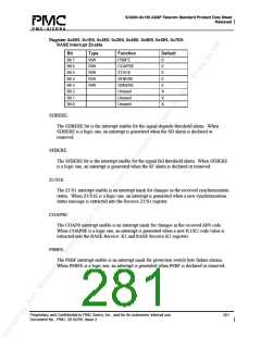
Register 0x0E0, 0x1E0, 0x2E0, 0x3E0, 0x4E0, 0x5E0, 0x6E0, 0x7E0:
RASE Interrupt Enable
Bit
Type
R/W
R/W
R/W
R/W
R/W
Function
PSBFE
COAPSE
Z1/S1E
SFBERE
SDBERE
Unused
Unused
Unused
Default
Bit 7
Bit 6
Bit 5
Bit 4
Bit 3
Bit 2
Bit 1
Bit 0
0
0
0
0
0
X
X
X
SDBERE:
The SDBERE bit is the interrupt enable for the signal degrade threshold alarm. When
SDBERE is a logic one, an interrupt is generated when the SD alarm is declared or
removed.
SFBERE:
The SFBERE bit is the interrupt enable for the signal fail threshold alarm. When SFBERE
is a logic one, an interrupt is generated when the SF alarm is declared or removed.
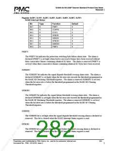
Z1/S1E:
The Z1/S1 interrupt enable is an interrupt mask for changes in the received synchronization
status. When Z1/S1E is a logic one, an interrupt is generated when a new synchronization
status message is extracted into the Receive Z1/S1 register.
COAPSE:
The COAPS interrupt enable is an interrupt mask for changes in the received APS code.
When COAPSE is a logic one, an interrupt is generated when a new K1/K2 code value is
extracted into the RASE Receive K1 and RASE Receive K2 registers.
PSBFE:
The PSBF interrupt enable is an interrupt mask for protection switch byte failure alarms.
When PSBFE is a logic one, an interrupt is generated when PSBF is declared or removed.
Proprietary and Confidential to PMC-Sierra, Inc., and for its customers’ internal use.
Document No.: PMC- 2010299, Issue 2
281

 PMC [ PMC-SIERRA, INC ]