Pm49FL002 / 004
PMC
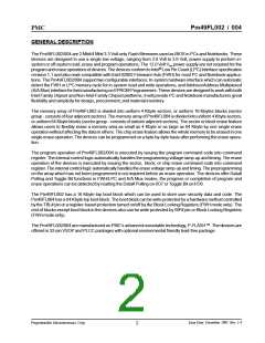
BLOCK DIAGRAM
ERASE/PROGRAM
VOLTAGE
GENERATOR
TBL#
WP#
INIT#
I/O BUFFERS
FWH[3:0] or
LAD[3:0]
FWH4 or LFRAME#
FWH/LPC
MODE
INTERFACE
HIGH VOLTAGE
SWITCH
CLK
GPI[4:0]
A[10:0]
I/O[7:0]
PP MODE
INTERFACE
WE#
OE#
R/C#
IC
CONTROL
LOGIC
DATA
LATCH
SENSE
AMP
RST#
Y-GATING
Y-DECODER
MEMORY
ARRAY
X-DECODER
DEVICE OPERATION
PRODUCT IDENTIFICATION
MODE SELECTION
The product identification mode can be used to read the
Manufacturer ID and the Device ID by a software Prod-
uct ID Entry command in both in-system hardware in-
terface and A/A Mux interface modes. The product
indentification mode is activated by three-bus-cycle com-
mand. Refer to Table 1 for the Manufacturer ID and De-
vice ID of Pm49FL00x and Table 14 for the SDP Com-
mand Definition.
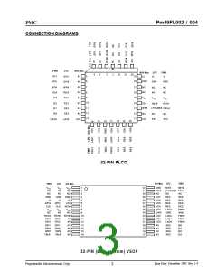
The Pm49FL002/004 can operate in two configurable
interfaces: The In-System Hardware interface and Ad-
dress/Address Multiplexed (A/A Mux) interface con-
trolled by IC pin. If the IC pin is set to logic high (VIH),
the devices enter into A/A Mux interface mode. If the IC
pin is set logic low (VIL), the devices will be in in-system
hardware interface mode. During the in-system hard-
ware interface mode, the devices can automatically de-
tect the Firmware Hub (FWH) or Low Pin Count (LPC)
memory cycle sent from host system and response to
the command accordingly. The IC pin must be setup
during power-up or system reset, and stays no change
during device operation.
In FWH mode, the product identification can also be
read directly at FFBC0000h for Manufacturer ID - “9Dh”
and FFBC0001h for Device ID in the 4 GByte system
memory map.
When working in-system, typically on a PC or Note-
book, the Pm49FL002/004 are connected to the host
system through a 5-pin communication interface oper-
ated based on a 33-MHz synchronous clock. The 5-pin
interface is defined as FWH[3:0] and FWH4 pins under
FWH mode or as LAD[3:0] and LFRAME# pins under
LPC mode for easy understanding as to those existing
compatible products. When working off-system, typi-
cally on a EPROM Programmer, the devices are oper-
ated through 11-pin multiplexed address - A[10:0] and
8-pin data I/O - I/O[7:0] interfaces. The memory ad-
dresses of devices are input through two bus cycles as
row and column addresses controlled by a R/C# pin.
Table 1: Product Identification
Description
Address
Data
00000h
00002h
9Dh
7Fh
Manufacturer ID
Device ID
Pm49FL002
Pm49FL004
2Mb
4Mb
00001h
6Dh
6Eh
Issue Date: December, 2003 Rev: 1.4
Programmable Microelectronics Corp.
6

 PMC [ PMC-SIERRA, INC ]