Software Architecture
PLX Technology, Inc.
7.3
Sample Configuration Procedure
Consideration must be given to the configuration procedure when setting up and initializing a PEX 8532
switch. Certain items are processed by initial hardware configuration, connections, and operating
selections. The PCI/PCI-Express Configuration software can be written from the Host, by way of the
upstream port to all downstream ports and their links, or from a serial EEPROM, by way of the serial
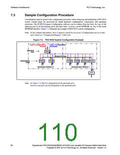
EEPROM interface. Figure 7-2 illustrates an example of PEX 8532 system configuration.
Note: In the example that follows, Port 3 registers cannot be accessed. A Configuration access to this
port returns an “Unsupported Request” (UR) error.
Figure 7-2. PEX 8532 System Configuration Example
Type 0 Configuration
Access
Type 1 Configuration
Accesses
Upstream
Port
Port 0
Virtual PCI Bus
Port 1
Port 2
Port 8
Port 9
Port 10 Port 11
Downstream
Ports
Upstream Station 0
Downstream Station 1
P-P
Note: In Figure 7-2, Port 0 is designated as the upstream port;
however, any port can be designated as the upstream port.
88
ExpressLane PEX 8532AA/BA/BB/BC 8-Port/32-Lane Versatile PCI Express Switch Data Book
Copyright © 2007 by PLX Technology, Inc. All Rights Reserved – Version 1.6

 PLX [ PLX TECHNOLOGY ]