Philips Semiconductors
Product specification
High speed CAN transceiver
TJA1041A
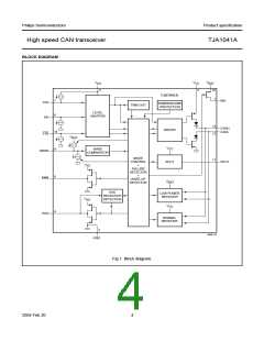
handbook, full pagewidth
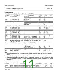
STB = H
and
EN = H
STB = H
and
EN = L
PWON/LISTEN-
ONLY MODE
NORMAL
MODE
STB = H
and
EN = H
STB = H
and
STB = H
EN = L
STB = H
and
EN = H
and
EN = L
STB = L
and
(EN = L or flag set)
STB = L
and
EN = H
STB = L and EN = H
and
flags cleared
STB = L
and
EN = L
GO-TO-SLEEP
COMMAND
MODE
STB = L and EN = H
and
STANDBY
MODE
flags cleared
STB = L
and
(EN = L or flag set)
flags cleared
and
STB = L
STB = H and EN = H
and
STB = H and EN = L
and
and
t > t
flag set
h(min)
UV
cleared
UV
cleared
NOM
NOM
SLEEP
MODE
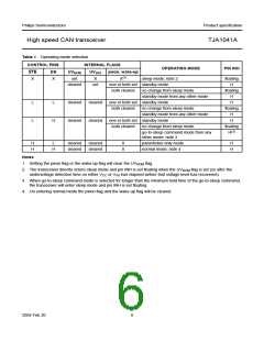
LEGEND:
MGU983
= H, = L
flag set
logical state of pin
setting pwon and/or wake-up flag
pwon and wake-up flag both cleared
flags cleared
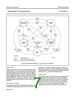
Fig.3 Mode transitions when VCC, VI/O and VBAT are present.
NORMAL MODE
behaviour. The receiver will still convert the analog bus
signal on pins CANH and CANL into digital data, available
for output to pin RXD. As in normal mode the bus pins are
biased at 0.5VCC, and pin INH remains active.
Normal mode is the mode for normal bi-directional CAN
communication. The receiver will convert the differential
analog bus signal on pins CANH and CANL into digital
data, available for output to pin RXD. The transmitter will
convert digital data on pin TXD into a differential analog
signal, available for output to the bus pins. The bus pins
are biased at 0.5VCC (via Ri(cm)). Pin INH is active, so
voltage regulators controlled by pin INH (see Fig.4) will be
active too.
STANDBY MODE
The standby mode is the first-level power saving mode of
the transceiver, offering reduced current consumption.
In standby mode the transceiver is not able to transmit or
receive data and the low-power receiver is activated to
monitor bus activity. The bus pins are biased at ground
level (via Ri(cm)). Pin INH is still active, so voltage
PWON/LISTEN-ONLY MODE
regulators controlled by this pin INH will be active too.
In pwon/listen-only mode the transmitter of the transceiver
is disabled, effectively providing a transceiver listen-only
2004 Feb 20
7

 NXP [ NXP ]