Philips Semiconductors
Preliminary specification
Sound fader control circuit
TEA6320
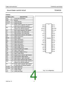
and TL and TR are inputs for inserting an external
FUNCTIONAL DESCRIPTION
equalizer.
The source selector selects one of 4 stereo inputs or the
mono input. The maximum input signal voltage is
The last section of the circuit is the volume II block. The
balance and fader functions are performed using the same
control blocks. This is realized by 4 independently
controllable attenuators, one for each output. The control
range of these attenuators is 55 dB in steps of 1 dB with an
additional mute step.
V
i(rms) = 2 V. The outputs of the source selector and the
inputs of the following volume control parts are available at
pins 8 and 10 for the left channel and pins 23 and 25 for
the right channel. This offers the possibility of interfacing a
noise reduction system.
The circuit provides 3 mute modes:
The volume control function is split into two sections:
volume I control block and volume II control block.
1. Zero crossing mode mute via I2C-bus using
2 independent zero crossing detectors (ZCM,
see Tables 2 and 9 and Fig.16).
The control range of volume I is between +20 dB and
−31 dB in steps of 1 dB. The volume II control range is
between 0 dB and −55 dB in steps of 1 dB. Although the
theoretical possible control range is 106 dB
(+20 to −86 dB), in practice a range of 86 dB (+20 to
−66 dB) is recommended. The gain/attenuation setting of
the volume I control block is common for both channels.
2. Fast mute via MUTE pin (see Fig.10).
3. Fast mute via I2C-bus either by general mute (GMU,
see Tables 2 and 9) or volume II block setting
(see Table 4).
The mute function is performed immediately if ZCM is
cleared (ZCM = 0). If the bit is set (ZCM = 1) the mute is
activated after changing the GMU bit. The actual mute
switching is delayed until the next zero crossing of the
audio frequency signal. As the two audio channels (left and
right) are independent, two comparators are built-in to
control independent mute switches.
The volume I control block operates in combination with
the loudness control. The filter is linear when the maximum
gain for the volume I control (+20 dB) is selected. The filter
characteristic increases automatically over a range of
32 dB down to a setting of −12 dB. That means the
maximum filter characteristic is obtained at −12 dB setting
of volume I. Further reduction of the volume does not
further influence the filter characteristic (see Fig.5). The
maximum selected filter characteristic is determined by
external components. The proposed application gives a
maximum boost of 17 dB for bass and 4.5 dB for treble.
The loudness may be switched on or off via I2C-bus control
(see Table 7).
To avoid a large delay of mute switching when very low
frequencies are processed, the maximum delay time is
limited to typically 100 ms by an integrated timing circuit
and an external capacitor (Cm = 10 nF, see Fig.10). This
timing circuit is triggered by reception of a new data word
for the switch function which includes the GMU bit. After a
discharge and charge period of an external capacitor the
muting switch follows the GMU bit if no zero crossing was
detected during that time.
The volume I control block is followed by the bass control
block. A single external capacitor of 33 nF for each
channel in combination with internal resistors, provides the
frequency response of the bass control (see Fig.3). The
adjustable range is between −15 and +15 dB at 40 Hz.
The mute function can also be controlled externally. If the
mute pin is switched to ground all outputs are muted
immediately (hardware mute). This mute request
overwrites all mute controls via the I2C-bus for the time the
pin is held LOW. The hardware mute position is not stored
in the TEA6320.
Both loudness and bass control result in a maximum bass
boost of 32 dB for low volume settings.
The treble control block offers a control range between
−12 and +12 dB in steps of 1.5 dB at 15 kHz. The filter
characteristic is determined by a single capacitor of 5.6 nF
for each channel in combination with internal resistors
(see Fig.4).
For the turn on/off behaviour the following explanation is
generally valid. To avoid AF output caused by the input
signal coming from preceding stages, which produces
output during drop of VCC, the mute has to be set, before
the VCC will drop. This can be achieved by I2C-bus control
or by grounding the MUTE pin.
The basic step width of bass and treble control is 3 dB. The
intermediate steps are obtained by switching 1.5 dB boost
and 1.5 dB attenuation steps.
For use where is no mute in the application before turn off,
a supply voltage drop of more than 1 × VBE will result in a
mute during the voltage drop.
The bass and treble control functions can be switched off
via I2C-bus. In this event the internal signal flow is
disconnected. The connections B2L and B2R are outputs
1995 Dec 19
5

 NXP [ NXP ]