TEA1532
Philips Semiconductors
GreenChip II SMPS control IC
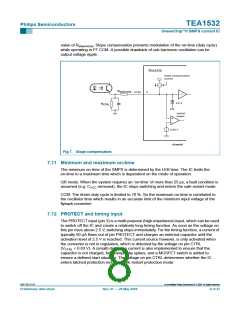
• When the voltage on pin CTRL is below 0.63 V, the IC is assumed to be out of
regulation (e.g. the control loop is open). In this case activating pin PROTECT
(VPROTECT > 2.5 V) will cause the converter to stop switching. Once VCC drops below
VUVLO, capacitor CVCC will be recharged and the supply will restart. This cycle will be
repeated until the fault condition is removed (safe restart mode)
• When the voltage on pin CTRL is above 0.63 V, the IC is assumed to be in regulation.
In this case activating pin PROTECT (VPROTECT > 2.5 V), by external means, will latch
the IC: The voltage on pin VCC will cycle between Vstart and VUVLO, but the IC will not
start switching again until the latch function is reset. The latch is reset as soon as VCC
drops below 4.5 V (typical value). The internal overtemperature protection will also
trigger this latch; see also Figure 1.
A voltage higher than 3 V on pin PROTECT will always latch the IC. This is independent of
the state of the IC.
7.13 Valley switching
Refer to Figure 8. A new cycle starts when the power switch is activated. After the on-time
(determined by the sense voltage and the internal control voltage), the switch is opened
and the secondary stroke starts. After the secondary stroke, the drain voltage shows an
1
oscillation with a frequency of approximately
-------------------------------------------------
(2 × π × (L × C )
p
d
where Lp is the primary self inductance of the transformer and Cd is the capacitance on
the drain node.
As soon as the oscillator voltage is high again and the secondary stroke has ended, the
circuit waits for the lowest drain voltage before starting a new primary stroke. This method
is called valley detection. Figure 8 shows the drain voltage, valley signal, secondary stroke
signal and the oscillator signal.
In an optimum design, the reflected secondary voltage on the primary side will force the
drain voltage to zero. Thus, zero voltage switching is possible, preventing large capacitive
1
2
2
switching losses P = × C × V × f , and allowing high frequency operation, which
--
results in small and cost effective magnetics.
9397 750 13113
© Koninklijke Philips Electronics N.V. 2004. All rights reserved.
Preliminary data sheet
Rev. 01 — 28 May 2004
9 of 27

 NXP [ NXP ]